| 33 |
| SA1 | 34 |
|
| CABLE_80P |
| ||
| 35 |
| SA0 | 36 |
|
| SA2 |
| ||
| 37 |
| HDC CS0# | 38 |
|
| HDC CS1# |
| ||
| 39 |
| HDD ACTIVE# | 40 |
|
| GROUND |
| ||
| 41 |
| VCC5 | 42 |
|
| VCC5 |
| ||
| 43 |
| GND | 44 |
|
|
|
| ||
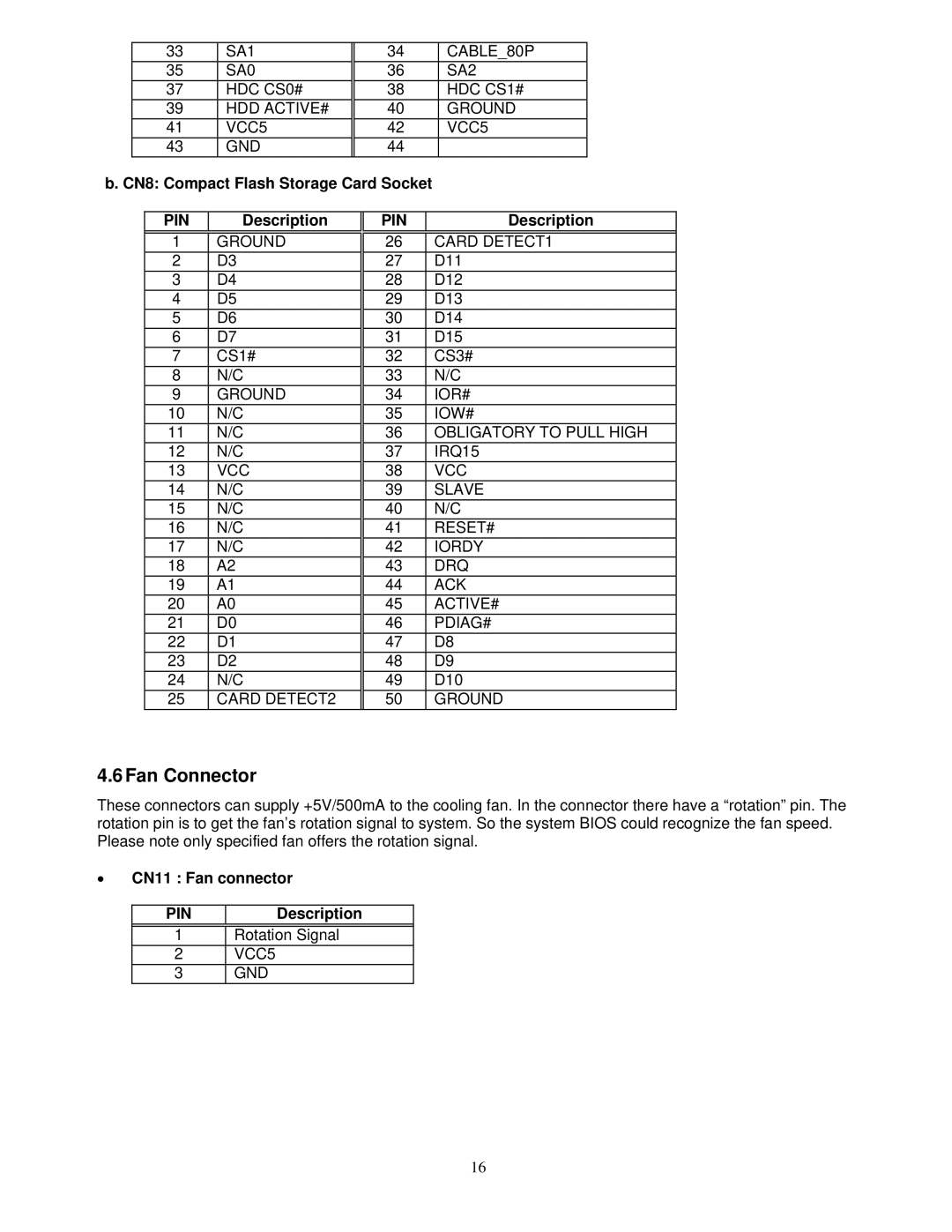
b. CN8: Compact Flash Storage Card Socket |
|
|
| |||||||
|
|
|
|
|
|
|
|
|
| |
|
| PIN |
| Description |
| PIN |
|
| Description | |
|
|
|
|
|
|
|
| |||
|
| 1 | GROUND |
| 26 |
| CARD DETECT1 | |||
|
| 2 | D3 |
| 27 |
| D11 | |||
|
| 3 | D4 |
| 28 |
| D12 | |||
|
| 4 | D5 |
| 29 |
| D13 | |||
|
| 5 | D6 |
| 30 |
| D14 | |||
|
| 6 | D7 |
| 31 |
| D15 | |||
|
| 7 | CS1# |
| 32 |
| CS3# | |||
|
| 8 | N/C |
| 33 |
| N/C | |||
|
| 9 | GROUND |
| 34 |
| IOR# | |||
|
| 10 | N/C |
| 35 |
| IOW# | |||
|
| 11 | N/C |
| 36 |
| OBLIGATORY TO PULL HIGH | |||
|
| 12 | N/C |
| 37 |
| IRQ15 | |||
|
| 13 | VCC |
| 38 |
| VCC | |||
|
| 14 | N/C |
| 39 |
| SLAVE | |||
|
| 15 | N/C |
| 40 |
| N/C | |||
|
| 16 | N/C |
| 41 |
| RESET# | |||
|
| 17 | N/C |
| 42 |
| IORDY | |||
|
| 18 | A2 |
| 43 |
| DRQ | |||
|
| 19 | A1 |
| 44 |
| ACK | |||
|
| 20 | A0 |
| 45 |
| ACTIVE# | |||
|
| 21 | D0 |
| 46 |
| PDIAG# | |||
|
| 22 | D1 |
| 47 |
| D8 | |||
|
| 23 | D2 |
| 48 |
| D9 | |||
|
| 24 | N/C |
| 49 |
| D10 | |||
|
| 25 | CARD DETECT2 |
| 50 |
| GROUND | |||
4.6Fan Connector
These connectors can supply +5V/500mA to the cooling fan. In the connector there have a “rotation” pin. The rotation pin is to get the fan’s rotation signal to system. So the system BIOS could recognize the fan speed. Please note only specified fan offers the rotation signal.
•CN11 : Fan connector
PIN | Description |
1Rotation Signal
2VCC5
3GND
16