CHAPTER 3 WIRING, CONNECTING
3.1 Physical interface
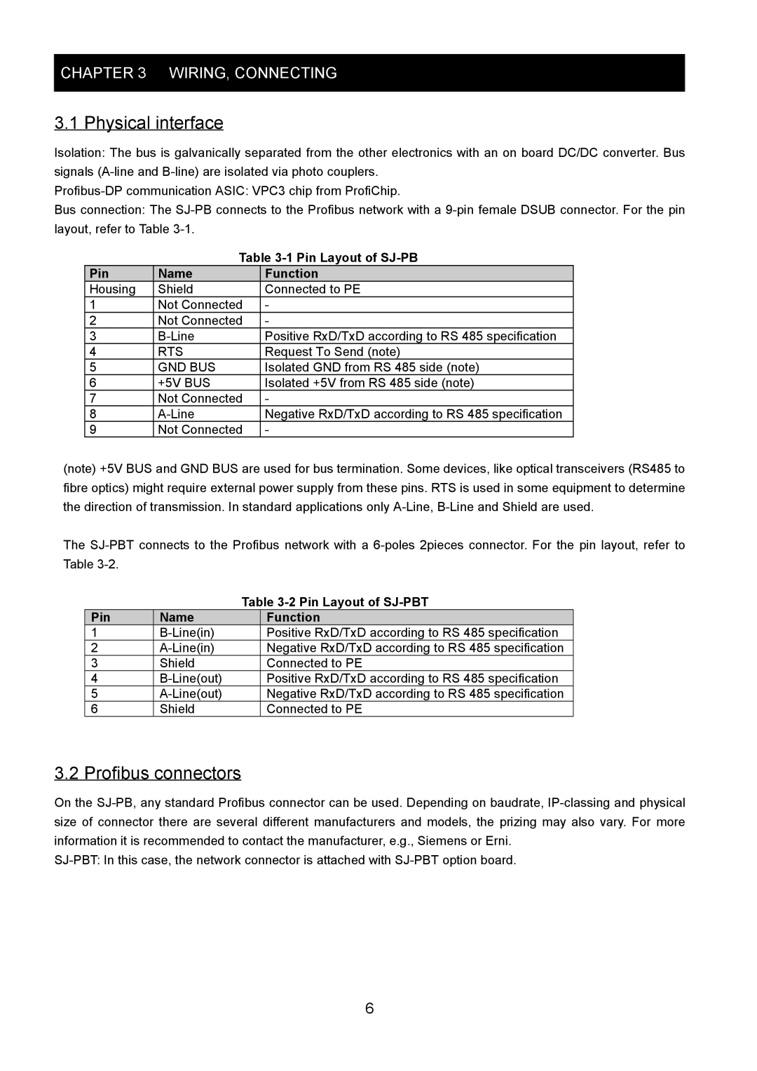
Isolation: The bus is galvanically separated from the other electronics with an on board DC/DC converter. Bus signals
Bus connection: The
Table 3-1 Pin Layout of SJ-PB
Pin | Name | Function |
Housing | Shield | Connected to PE |
1 | Not Connected | - |
2 | Not Connected | - |
3 | Positive RxD/TxD according to RS 485 specification | |
4 | RTS | Request To Send (note) |
5 | GND BUS | Isolated GND from RS 485 side (note) |
6 | +5V BUS | Isolated +5V from RS 485 side (note) |
7 | Not Connected | - |
8 | Negative RxD/TxD according to RS 485 specification | |
9 | Not Connected | - |
(note) +5V BUS and GND BUS are used for bus termination. Some devices, like optical transceivers (RS485 to fibre optics) might require external power supply from these pins. RTS is used in some equipment to determine the direction of transmission. In standard applications only
The
|
| Table | |
Pin | Name |
| Function |
1 |
| Positive RxD/TxD according to RS 485 specification | |
2 |
| Negative RxD/TxD according to RS 485 specification | |
3 | Shield |
| Connected to PE |
4 |
| Positive RxD/TxD according to RS 485 specification | |
5 |
| Negative RxD/TxD according to RS 485 specification | |
6 | Shield |
| Connected to PE |
3.2 Profibus connectors
On the
6
