CHAPTER5 OPERATING
In the request message the first two bytes are used for parameter identification. The first digit (7) denotes the function “Change parameter value (array word)” (refer to chapter 3.2). The second digit along with the second byte (3 and 93) indicates parameter number 916. Byte 3 (01) denotes
In the response message, the first digit (4) indicates the function “Transfer parameter value (array word)”. Sub- index (01 00), value (00 3D in bytes 7 and 8) and parameter number (x3 94) are mirrored from the request. In the PZD3 field (word 7) the value (01 F4 = 500dec, 5.00 Hz) of “Jogging frequency” is transferred.
5.4.3 Writing a two byte array parameter #2
In this third example, we are configuring PZD3 to contain the value of parameter A004, “1st Maximum frequency” in the request from the master to the inverter. PPO2 is used. On Profibus parameter A004 corresponds to parameter number 62 (3Eh). This is configured with parameter number 915 (393h), “Assignment of PZD write word” (see also chapter 5.3.3 and 5.5).
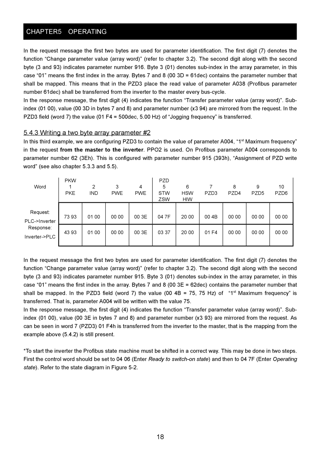
Word
Request:
Response:
PKW |
|
|
| PZD |
|
|
|
|
|
1 | 2 | 3 | 4 | 5 | 6 | 7 | 8 | 9 | 10 |
PKE | IND | PWE | PWE | STW | HSW | PZD3 | PZD4 | PZD5 | PZD6 |
|
|
|
| ZSW | HIW |
|
|
|
|
73 93 | 01 00 | 00 00 | 00 3E | 04 7F | 20 00 | 00 4B | 00 00 | 00 00 | 00 00 |
|
|
|
|
|
|
|
|
|
|
43 93 | 01 00 | 00 00 | 00 3E | 03 37 | 20 00 | 01 F4 | 00 00 | 00 00 | 00 00 |
|
|
|
|
|
|
|
|
|
|
In the request message the first two bytes are used for parameter identification. The first digit (7) denotes the function “Change parameter value (array word)” (refer to chapter 3.2). The second digit along with the second byte (3 and 93) indicates parameter number 915. Byte 3 (01) denotes
In the response message, the first digit (4) indicates the function “Transfer parameter value (array word)”. Sub- index (01 00), value (00 3E in bytes 7 and 8) and parameter number (x3 93) are mirrored from the request. As can be seen in word 7 (PZD3) 01 F4h is transferred from the inverter to the master, that is the mapping from the example above (5.4.2) is still present.
*To start the inverter the Profibus state machine must be shifted in a correct way. This may be done in two steps. First the control word should be set to 04 06 (Enter Ready to
18