CHAPTER 6 COUNTERMEASURE FOR ABNORMALY
6.1 Trip display
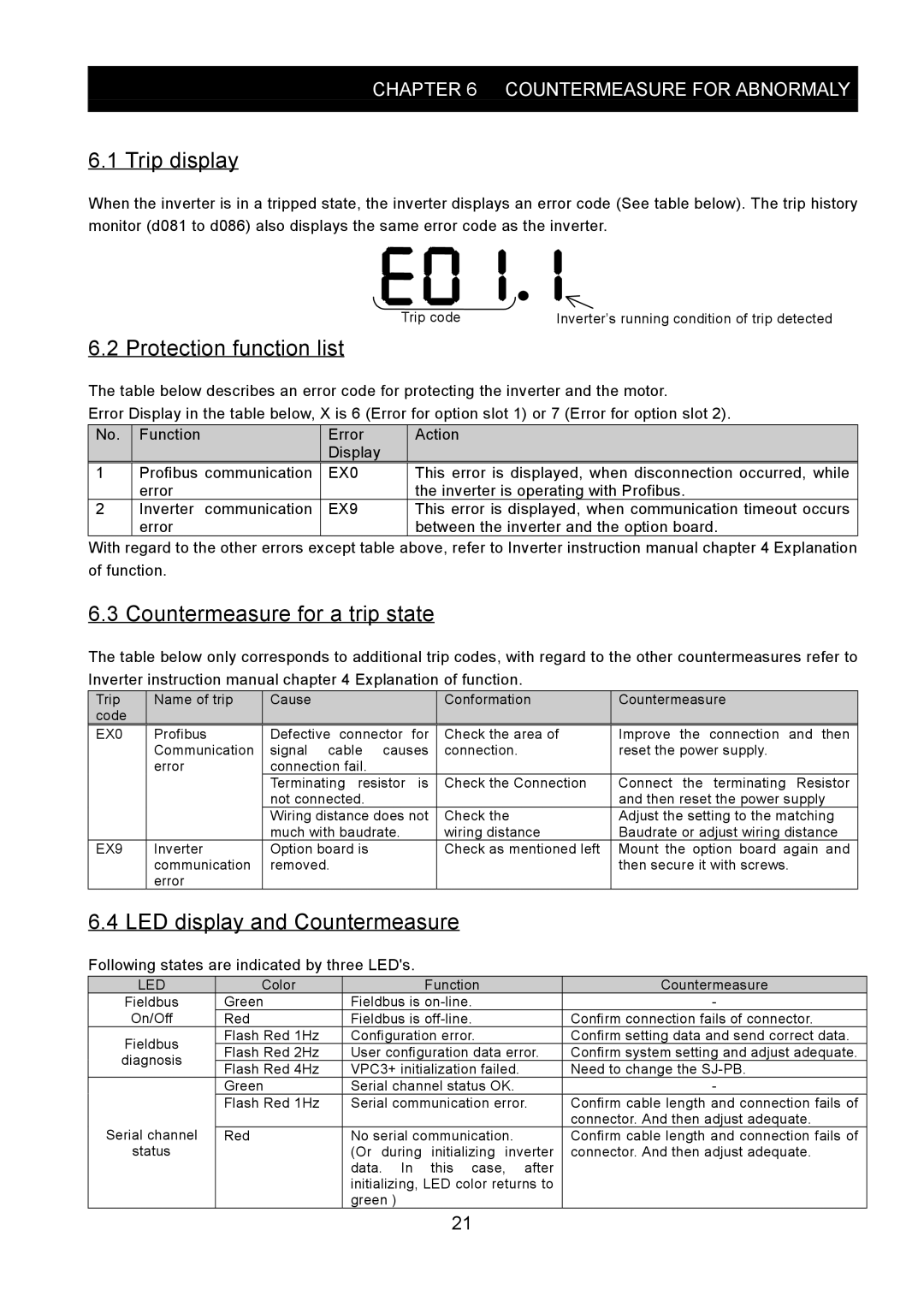
When the inverter is in a tripped state, the inverter displays an error code (See table below). The trip history monitor (d081 to d086) also displays the same error code as the inverter.
Trip code | Inverter’s running condition of trip detected |
6.2 Protection function list
The table below describes an error code for protecting the inverter and the motor.
Error Display in the table below, X is 6 (Error for option slot 1) or 7 (Error for option slot 2).
No. | Function | Error | Action |
|
| Display |
|
1 | Profibus communication | EX0 | This error is displayed, when disconnection occurred, while |
| error |
| the inverter is operating with Profibus. |
2 | Inverter communication | EX9 | This error is displayed, when communication timeout occurs |
| error |
| between the inverter and the option board. |
With regard to the other errors except table above, refer to Inverter instruction manual chapter 4 Explanation of function.
6.3 Countermeasure for a trip state
The table below only corresponds to additional trip codes, with regard to the other countermeasures refer to Inverter instruction manual chapter 4 Explanation of function.
Trip | Name of trip | Cause |
| Conformation | Countermeasure |
code |
|
|
|
|
|
EX0 | Profibus | Defective connector | for | Check the area of | Improve the connection and then |
| Communication | signal cable causes | connection. | reset the power supply. | |
| error | connection fail. |
|
|
|
|
| Terminating resistor | is | Check the Connection | Connect the terminating Resistor |
|
| not connected. |
|
| and then reset the power supply |
|
| Wiring distance does not | Check the | Adjust the setting to the matching | |
|
| much with baudrate. |
| wiring distance | Baudrate or adjust wiring distance |
EX9 | Inverter | Option board is |
| Check as mentioned left | Mount the option board again and |
| communication | removed. |
|
| then secure it with screws. |
| error |
|
|
|
|
6.4 LED display and Countermeasure
Following states are indicated by three LED's.
LED | Color |
| Function | Countermeasure | |
Fieldbus | Green | Fieldbus is | - | ||
On/Off | Red | Fieldbus is | Confirm connection fails of connector. | ||
Fieldbus | Flash Red 1Hz | Configuration error. | Confirm setting data and send correct data. | ||
Flash Red 2Hz | User configuration data error. | Confirm system setting and adjust adequate. | |||
diagnosis | |||||
Flash Red 4Hz | VPC3+ initialization failed. | Need to change the | |||
| |||||
| Green | Serial channel status OK. | - | ||
| Flash Red 1Hz | Serial communication error. | Confirm cable length and connection fails of | ||
Serial channel |
|
|
| connector. And then adjust adequate. | |
Red | No serial communication. | Confirm cable length and connection fails of | |||
status |
| (Or during | initializing inverter | connector. And then adjust adequate. | |
|
| data. In | this case, after |
| |
|
| initializing, LED color returns to |
| ||
|
| green ) |
|
| |
21