Internal cable connections
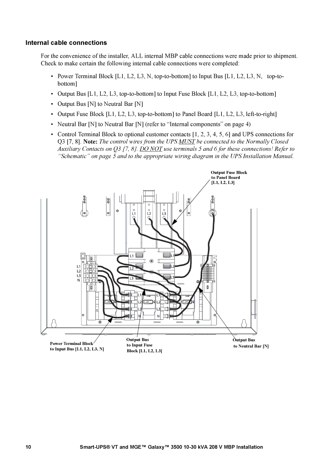
For the convenience of the installer, ALL internal MBP cable connections were made prior to shipment. Check to make certain the following internal cable connections were completed:
• Power Terminal Block [L1, L2, L3, N,
•Output Bus [L1, L2, L3,
•Output Bus [N] to Neutral Bar [N]
•Output Fuse Block [L1, L2, L3,
•Neutral Bar [N] to Neutral Bar [N] (refer to “Internal components” on page 4)
•Control Terminal Block to optional customer contacts [1, 2, 3, 4, 5, 6] and UPS connections for Q3 [7, 8]. Note: The control wires from the UPS MUST be connected to the Normally Closed Auxiliary Contacts on Q3 [7, 8]. DO NOT use terminals 5 and 6 for these connections! Refer to “Schematic” on page 5 and to the appropriate wiring diagram in the UPS Installation Manual.
Output Fuse Block to Panel Board [L1, L2, L3]
Power | Terminal Block | Output Bus | Output Bus |
to Input Fuse | to Neutral Bar [N] | ||
to Input | Bus [L1, L2, L3, N] | Block [L1, L2, L3] |
|
|
|
|
10 |