Making external cable connections
Note: Utility cables can enter through the top or the bottom of the MBP. However, BOTTOM is recommended.
External cables can enter the MBP through any of the available
Prior to making any of the following external cable connections, establish an appropriate point of access by knocking out a
The cables are typically color coded: L1 = black, L2 = red, L3 = blue, N = white, and G = green.
Utility connections.
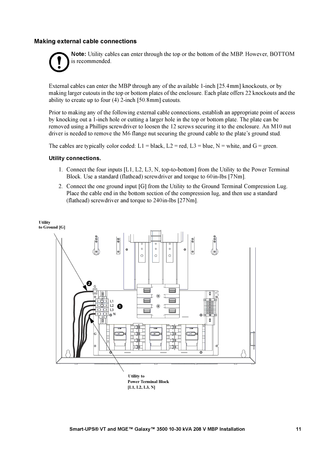
1.Connect the four inputs [L1, L2, L3, N,
2.Connect the one ground input [G] from the Utility to the Ground Terminal Compression Lug. Place the cable end in the bottom section of the compression lug, and then use a standard (flathead) screwdriver and torque to
Utility
to Ground [G]
G
Utility to
Power Terminal Block [L1, L2, L3, N]
11 |
