Front and Rear Panel
Components
Front panel
Use the toolless mounting pegs on the front panel of the Main Module to install it in an APC rack or enclosure without using any
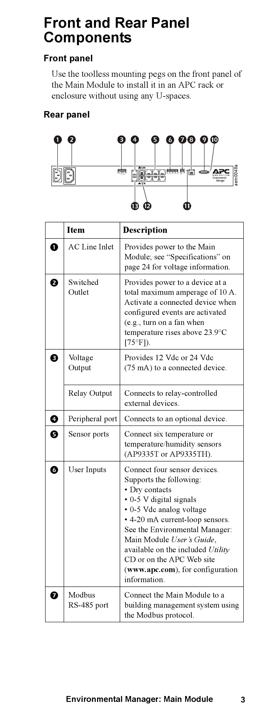
Rear panel
+G NC N 2412+ N OO C
D M
|
|
|
|
1 | 2 | 3 | 4 |
+– | +– | +– | +– |
GD D N0 1 D
Environmental
Manager
aem0048a
| Item | Description |
|
|
|
| AC Line Inlet | Provides power to the Main |
|
| Module; see “Specifications” on |
|
| page 24 for voltage information. |
|
|
|
| Switched | Provides power to a device at a |
| Outlet | total maximum amperage of 10 A. |
|
| Activate a connected device when |
|
| configured events are activated |
|
| (e.g., turn on a fan when |
|
| temperature rises above 23.9°C |
|
| [75°F]). |
|
|
|
| Voltage | Provides 12 Vdc or 24 Vdc |
| Output | (75 mA) to a connected device. |
|
|
|
| Relay Output | Connects to |
|
| external devices. |
|
|
|
| Peripheral port | Connects to an optional device. |
|
|
|
| Sensor ports | Connect six temperature or |
|
| temperature/humidity sensors |
|
| (AP9335T or AP9335TH). |
|
|
|
| User Inputs | Connect four sensor devices. |
|
| Supports the following: |
|
| • Dry contacts |
|
| • |
|
| • |
|
| • |
|
| See the Environmental Manager: |
|
| Main Module User’s Guide, |
|
| available on the included Utility |
|
| CD or on the APC Web site |
|
| (www.apc.com), for configuration |
|
| information. |
|
|
|
| Modbus | Connect the Main Module to a |
| building management system using | |
|
| the Modbus protocol. |
|
|
|
Environmental Manager: Main Module | 3 |
