❏4. Install the prop saver onto the gearbox output shaft. The screws should seat down into the flat spots on the shaft. Add a drop of
Final Setup
❏1. Attach the receiver to the cutout in the rear of the fuselage using a small section of the supplied hook and loop tape. Place the rough, or “hook” side of the tape into the cutout in the fuselage and the soft “loop” side of the tape on the back of the receiver.
❏2. Connect the servos and ESC to their channels on the receiver. You will need to use extensions to allow the aileron servo and ESC leads to reach the receiver. Use a 6" [153 mm] extension for the aileron servo lead, and a 12" [305 mm] extension for the ESC. Route the servo leads through the
❏3. Power up your radio system and center the servos. If necessary, adjust the center point of the control surfaces by tightening or enlarging the
❏4. Locate the 1" [25 mm] plastic streamer mount. Mark the approximate midpoint of the mount.
❏5. Cut a 1" [25 mm] slot in the bottom of the fuselage at the tail as shown. The exact location is not important; it simply needs to be at the tail of the fuselage. Do not attach the mount to the rudder control surface.
❏6. Test fit the mount in the groove. It should insert up to the midpoint line. Glue in place using epoxy.
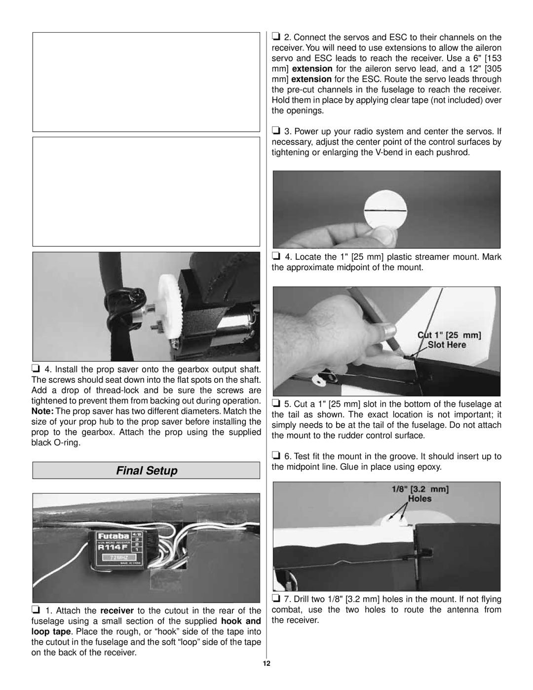
❏7. Drill two 1/8" [3.2 mm] holes in the mount. If not flying combat, use the two holes to route the antenna from the receiver.
12