Front and Rear Panels
The following sections describe the controls and indicators on the front and rear panels.
Front Panel Controls and Indicators
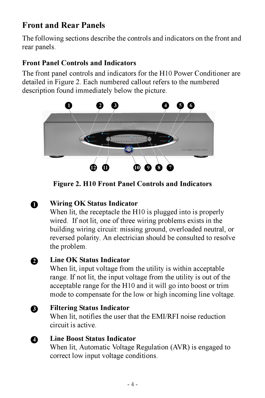
The front panel controls and indicators for the H10 Power Conditioner are detailed in Figure 2. Each numbered callout refers to the numbered description found immediately below the picture.
1 | 2 | 3 | 4 | 5 | 6 |
12 | 11 | 10 | 9 | 8 | 7 |
Figure 2. H10 Front Panel Controls and Indicators
1Wiring OK Status Indicator
When lit, the receptacle the H10 is plugged into is properly wired. If not lit, one of three wiring problems exists in the building wiring circuit: missing ground, overloaded neutral, or reversed polarity. An electrician should be consulted to resolve the problem.
2Line OK Status Indicator
When lit, input voltage from the utility is within acceptable range. If not lit, the input voltage from the utility is out of the acceptable range for the H10 and it will go into boost or trim mode to compensate for the low or high incoming line voltage.
3Filtering Status Indicator
When lit, notifies the user that the EMI/RFI noise reduction circuit is active.
4Line Boost Status Indicator
When lit, Automatic Voltage Regulation (AVR) is engaged to correct low input voltage conditions.
- 4 -
