Battery Installation
The UPS battery is shipped in a separate carton.
Refer to the installation guide included with the replacement battery for installation instructions.
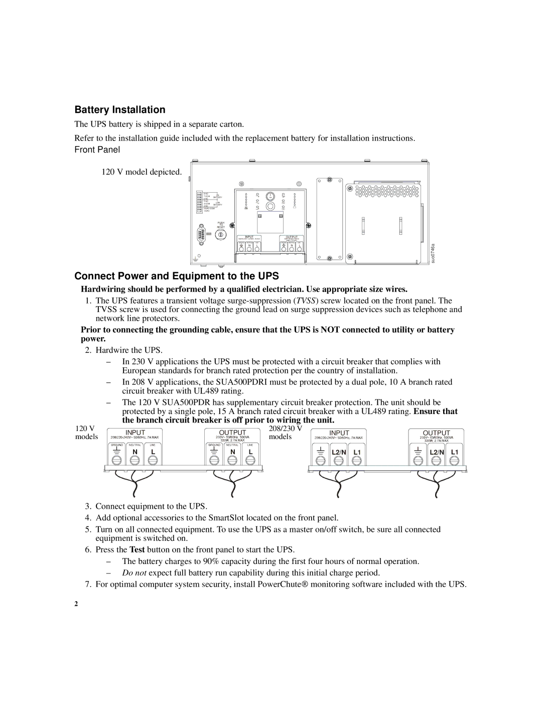
Front Panel
120 V model depicted.
8 NO | ON |
|
|
|
|
|
7 COM | BATTERY |
|
| Test |
|
|
6 NC |
|
|
|
| ||
|
|
|
|
|
| |
5 NO | LOW |
|
|
|
|
|
4 COM |
|
|
|
|
| |
3 NC | BATTERY |
|
|
|
|
|
|
|
|
|
|
| |
2 EPO COM |
|
|
|
|
| |
1 EPO |
|
|
|
|
|
|
| PUSH |
|
|
|
|
|
| TO |
|
|
|
|
|
| RESET |
|
|
|
|
|
|
| INPUT |
| OUTPUT |
|
|
| 230V~ 50/60Hz, 500VA |
| ||||
|
|
|
| 325W, 2.7A MAX |
|
|
| GROUND | NEUTRAL | LINE | GROUND NEUTRAL | LINE | suo0746a |
|
| N | L | N | L | |
|
|
|
|
|
| |
Connect Power and Equipment to the UPS
Hardwiring should be performed by a qualified electrician. Use appropriate size wires.
1.The UPS features a transient voltage
Prior to connecting the grounding cable, ensure that the UPS is NOT connected to utility or battery power.
2.Hardwire the UPS.
–In 230 V applications the UPS must be protected wi th a circuit breaker that complies with European standards for branch rated protection per the country of installation.
120V
models
–In 208 V applications, the SUA500PDRI must be prot ected by a dual pole, 10 A branch rated circuit breaker with UL489 rating.
–The 120 V SUA500PDR has supplementary circuit brea ker protection. The unit should be protected by a single pole, 15 A branch rated circuit breaker with a UL489 rating. Ensure that
the branch circuit breaker is off prior to wiring the unit.
INPUT |
| OUTPUT |
| 208/230 V | INPUT | OUTPUT |
|
| models | ||||
|
|
|
|
|
| |
NEUTRAL | LINE | NEUTRAL | LINE |
|
|
|
N | L | N | L |
| L2/N L1 | L2/N L1 |
3.Connect equipment to the UPS.
4.Add optional accessories to the SmartSlot located on the front panel.
5.Turn on all connected equipment. To use the UPS as a master on/off switch, be sure all connected equipment is switched on.
6.Press the Test button on the front panel to start the UPS.
–The battery charges to 90% capacity during the fir st four hours of normal operation.
–Do not expect full battery run capability during this initial charge period.
7.For optimal computer system security, install PowerChute® monitoring software included with the UPS.
2