PRO1100e, PRO1300 TCE, PRO1300, PRO1100, PRO1100e TCE specifications
The AquaPRO PRO1300h/c TCE, PRO1300 TCE, PRO1100e TCE, PRO1100, and PRO1100e are a series of high-performance water treatment systems designed to meet the diverse needs of residential and commercial users. These models stand out due to their advanced technology, energy efficiency, and user-friendly operation, making them ideal for various water purification tasks.The AquaPRO PRO1300h/c TCE is equipped with advanced filtration technology that combines multiple filtration stages, ensuring the removal of contaminants, odors, and unpleasant tastes from the water. Its high-capacity system is perfect for larger households or small businesses, treating up to 1,300 gallons per day. This model features a compact design, which simplifies installation and saves valuable space, while providing a robust solution for clean drinking water.
The PRO1300 TCE model mirrors many features of the PRO1300h/c but is tailored for specific applications where heating or cooling functions are not necessary. It retains the high filtration capacity and incorporates smart technology that allows users to monitor water quality in real-time. The user-friendly interface and app connectivity offer convenient access to system status and maintenance alerts.
Moving down the range, the AquaPRO PRO1100e TCE offers slightly lower filtration capabilities but maintains the same commitment to quality and efficiency. Perfect for medium-sized households, the PRO1100e TCE boasts an eco-friendly design that minimizes energy consumption without compromising on performance. It features a smart leak detection system that alerts users in the event of any leaks, safeguarding both the unit and the property.
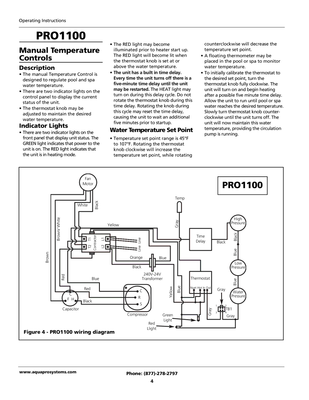
The PRO1100 is a more basic model intended for users seeking simplicity without sacrificing performance. It offers reliable filtration with easy-to-replace cartridges and minimal maintenance requirements, making it an excellent choice for those new to water filtration systems.
Lastly, the PRO1100e is designed for environments where energy efficiency is prioritized. Its reduced operational costs make it particularly attractive to eco-conscious consumers. With durable construction and a simple interface, these models ensure longevity and ease of use, appealing to a wide demographic.
In conclusion, the AquaPRO range encompasses various models, each with distinct features that cater to different filtration needs while ensuring high-quality performance, making the AquaPRO systems a wise investment for clean, safe water.

