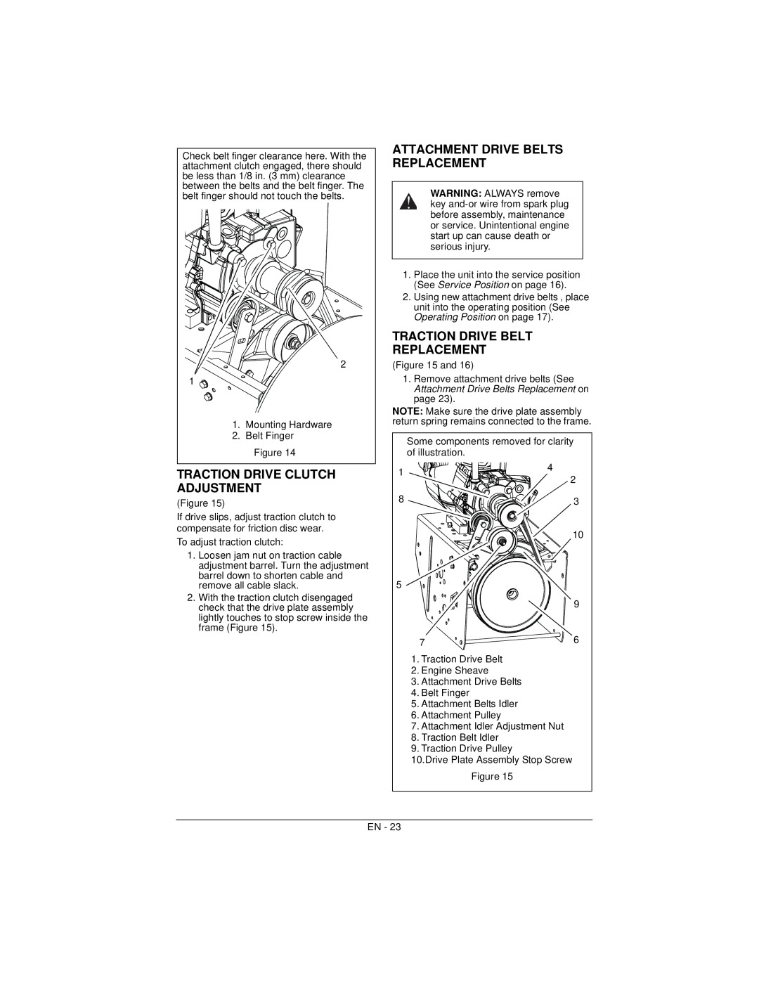
Check belt finger clearance here. With the attachment clutch engaged, there should be less than 1/8 in. (3 mm) clearance between the belts and the belt finger. The belt finger should not touch the belts.
2
1 ![]()
![]()
![]()
1.Mounting Hardware
2.Belt Finger
Figure 14
TRACTION DRIVE CLUTCH ADJUSTMENT
(Figure 15)
If drive slips, adjust traction clutch to compensate for friction disc wear.
To adjust traction clutch:
1.Loosen jam nut on traction cable adjustment barrel. Turn the adjustment barrel down to shorten cable and remove all cable slack.
2.With the traction clutch disengaged check that the drive plate assembly lightly touches to stop screw inside the frame (Figure 15).
ATTACHMENT DRIVE BELTS REPLACEMENT
WARNING: ALWAYS remove key
1.Place the unit into the service position (See Service Position on page 16).
2.Using new attachment drive belts , place unit into the operating position (See Operating Position on page 17).
TRACTION DRIVE BELT
REPLACEMENT
(Figure 15 and 16)
1.Remove attachment drive belts (See Attachment Drive Belts Replacement on page 23).
NOTE: Make sure the drive plate assembly return spring remains connected to the frame.
| Some components removed for clarity | |
| of illustration. |
|
1 | 4 | 2 |
| ||
|
| |
8 |
| 3 |
|
| 10 |
5 |
|
|
|
| 9 |
| 7 | 6 |
| 1. Traction Drive Belt |
|
| 2. Engine Sheave |
|
| 3. Attachment Drive Belts |
|
| 4. Belt Finger |
|
| 5. Attachment Belts Idler |
|
| 6. Attachment Pulley |
|
| 7. Attachment Idler Adjustment Nut |
|
| 8. Traction Belt Idler |
|
| 9. Traction Drive Pulley |
|
| 10.Drive Plate Assembly Stop Screw | |
| Figure 15 |
|
EN - 23
