OPERATION
WARNING: AVOID INJURY. Read and understand entire Safety section before proceeding.
CONTROLS AND FEATURES
NOTE: Read the attachment(s) and unit manuals before operating the equipment. Operate the unit only from the operator’s position, behind the handlebars. Service the unit and attachment before operating.
Refer to Controls and Features for the following.
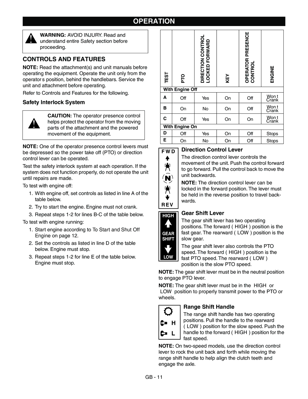
Safety Interlock System
CAUTION: The operator presence control helps protect the operator from the moving parts of the attachment and the powered movement of the equipment.
NOTE: One of the operator presence control levers must be depressed so the power take off (PTO) or direction
TEST | PTO |
| DIRECTION CONTROL LOCKED FORWARD | KEY | OPERATOR PRESENCE CONTROL | ENGINE |
|
|
|
|
|
|
|
With | Engine Off |
|
|
|
| |
A | Off |
| Yes | On | Off | Won’t |
|
|
|
|
|
| Crank |
B | On |
| No | On | Off | Won’t |
|
|
|
|
|
| Crank |
C | Off |
| Yes | On | On | Won’t |
|
|
|
|
|
| Crank |
With | Engine On |
|
|
|
| |
D | Off |
| Yes | On | Off | Stops |
E | On |
| No | On | Off | Stops |
F W D | Direction Control Lever |
|
control lever can be operated.
Test the safety interlock system at each operation. If the system does not function properly, do not operate the unit until repairs are made.
To test with engine off:
1. With engine off, set controls as listed in line A of the |
table below. |
N
The direction control lever controls the movement of the unit. Push the control forward to go forward. Pull the control back to move the unit backwards.
NOTE: The direction control lever can be locked in the forward position. The lever must be held in the reverse position to travel back- wards.
2. | Try to start the engine. Engine must not crank. |
3. | Repeat steps |
To test with engine running: | |
1.Start engine according to To Start and Shut Off Engine on page 12.
2.Set the controls as listed in line D of the table below. Engine must stop.
3.Repeat steps
R E V |
| |
HIGH | Gear Shift Lever | |
The gear shift lever has two operating | ||
| ||
| positions. The forward (“HIGH”) position is the | |
GEAR | fast gear. The rearward (“LOW”) position is the | |
SHIFT | slow gear. | |
| The gear shift lever also controls the PTO | |
LOW | speed. The forward (“HIGH”) position is the | |
fast PTO speed. The rearward (“LOW”) | ||
| position is the slow PTO speed. |
NOTE: The gear shift lever must be in the neutral position to engage PTO lever.
NOTE: The gear shift lever must be in the “HIGH” or
“LOW” position to properly transmit power to the PTO or wheels.
Range Shift Handle
The range shift handle has two operating
Hpositions. Pull the handle to the rearward
(“LOW”) position for the slow speed. Push the
|
| L | handle to the forward (“HIGH”) position for the |
|
| ||
|
| ||
|
|
| fast speed. |
|
|
|
NOTE: On
GB - 11