ASSEMBLY
Install Hubs and Wheels
For
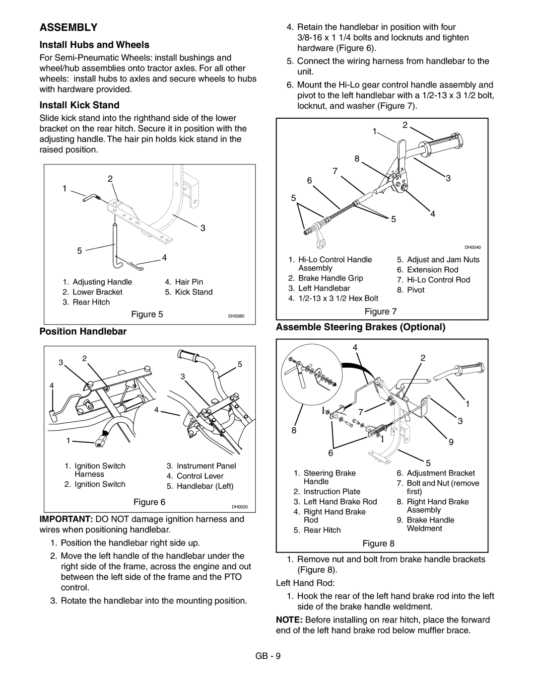
Install Kick Stand
Slide kick stand into the righthand side of the lower bracket on the rear hitch. Secure it in position with the adjusting handle. The hair pin holds kick stand in the raised position.
2
1
|
|
| 3 |
| 5 |
|
|
| 4 |
| |
1. | Adjusting Handle | 4. | Hair Pin |
2. | Lower Bracket | 5. | Kick Stand |
3. | Rear Hitch |
|
|
| Figure 5 |
| DH0080 |
Position Handlebar
3 | 2 |
5 | |
| 3 |
4 |
|
4.Retain the handlebar in position with four
5.Connect the wiring harness from handlebar to the unit.
6.Mount the
| 1 | 2 | |
|
|
| |
| 8 |
|
|
| 7 |
| 3 |
| 6 |
| |
5 |
|
|
|
| 5 |
| 4 |
|
|
| |
|
|
| DH0040 |
1. | 5. | Adjust and Jam Nuts | |
| Assembly | 6. | Extension Rod |
2. | Brake Handle Grip | 7. | |
3. | Left Handlebar | 8. | Pivot |
4. |
|
| |
| Figure 7 |
|
|
Assemble Steering Brakes (Optional)
4
2
|
| 4 |
|
1 |
|
|
|
1. | Ignition Switch | 3. | Instrument Panel |
| Harness | 4. | Control Lever |
2. | Ignition Switch | 5. | Handlebar (Left) |
|
| Figure 6 | DH0020 |
|
|
|
IMPORTANT: DO NOT damage ignition harness and wires when positioning handlebar.
7
8
6
1.Steering Brake Handle
2.Instruction Plate
3.Left Hand Brake Rod
4.Right Hand Brake Rod
5.Rear Hitch
1
3
9
5
6.Adjustment Bracket
7.Bolt and Nut (remove first)
8.Right Hand Brake Assembly
9.Brake Handle Weldment
1.Position the handlebar right side up.
2.Move the left handle of the handlebar under the right side of the frame, across the engine and out between the left side of the frame and the PTO control.
3.Rotate the handlebar into the mounting position.
Figure 8
1.Remove nut and bolt from brake handle brackets (Figure 8).
Left Hand Rod:
1.Hook the rear of the left hand brake rod into the left side of the brake handle weldment.
NOTE: Before installing on rear hitch, place the forward end of the left hand brake rod below muffler brace.
GB - 9