Duct Steam Distribution
1. The dispersion tube should be proper length. Verify correct size from Table 8-1.
2. Install dispersion tube(s) horizontally in duct so holes face upward. Air flow must be vertical up or
horizontal. Do not restrict duct with a height of 200 mm (8”) or less. Installations over 10 m/s
(2000 FPM) air velocity are not recommended. Consult factory if air flow is vertical down or air
velocity is over 10 m/s (2000 FPM). Do not install in ducted systems with static pressure exceeding
150 mm (6”).
3. The dispersion tube(s) should be located upstream of a straight duct run, without obstructions, 3 m
(10 feet) or more in length. Consult the factory if this distance is not available.
4. Use the template provided to cut dispersion tube installation holes. Fasten the mounting plate to
duct with sheet metal screws. If the dispersion tube is 900 mm (35”) or longer, support the far
end with threaded rod or similar means.
5. Note: For steam being generated from a deionized (DI) or reverse osmosis (RO) water source, the
use of 50 mm (2”) insulated stainless steel piping in lieu of copper is required. Pipe used for steam
dispersion piping must be oil and contaminate free. Premature element failure could result if oils or
contaminates are present. Contact the factory with questions. Connect dispersion tube(s) to
HumidiClean tank using 50 mm (2”) nominal insulated copper pipe and hose cuffs provided. We do
not suggest steam distribution piping of field supplied rubber based compounds to be used for any
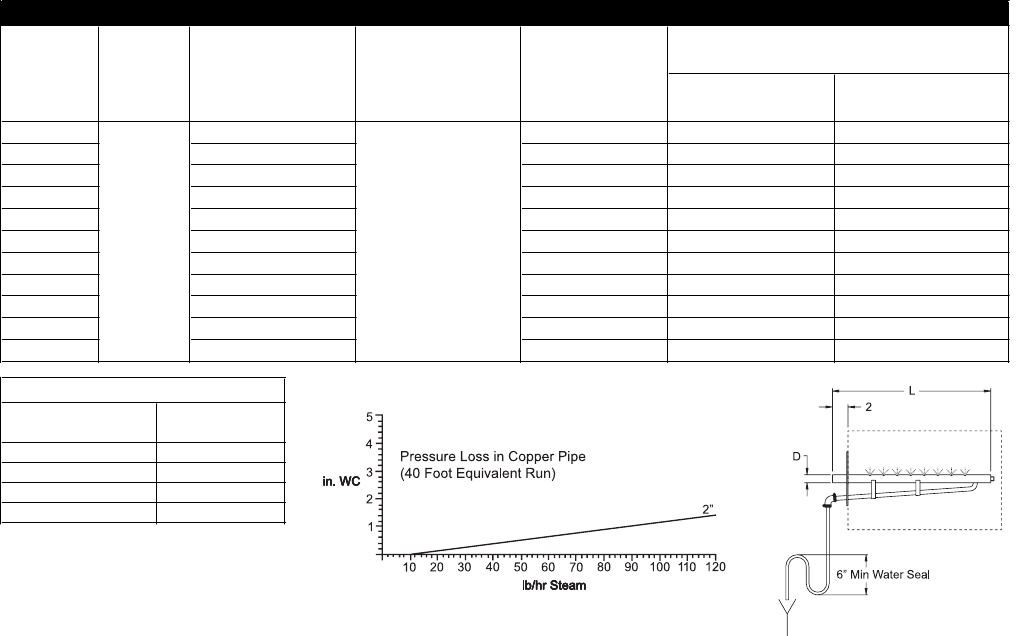
HumidiClean application. Pitch pipe back to unit 25 mm (1”) per foot. The steam pipe must be free
of kinks and sags to allow for gravity drainage of condensate. Maximum pipe run distance from
tank to dispersion tube is 12 m (40 feet) equivalent piping length. Avoid excessive use of elbows or
45°changes in direction. A"P" trap drain should be installed every 6 m (20 feet), of piping run or at
the bottom of vertical runs that cannot drain back to the tank. See Fig. 8-3 for "P" trap detail.
6. If duct static pressure plus piping back pressure is greater than 0.5 in HG (6" WC), please consult
the factory.
8
Figure 8-3
Figure 8-2
Minimum
mm (in)
Maximum
mm (in)
D-1 DL-1 305 (12) 280 (11) 406 (16)
D-1.5 DL-1.5 457 (18) 432 (17) 559 (22)
D-2 DL-2 610 (24) 584 (23) 864 (34)
D-3 DL-3 914 (36) 889 (35) 1168 (46)
D-4 DL-4 1219 (48) 1194 (47) 1473 (58)
D-5 DL-5 1524 (60) 1499 (59) 1778 (70)
D-6 DL-6 1829 (72) 1803 (71) 2083 (82)
D-7 DL-7 2133 (84) 2108 (83) 2388 (94)
D-8 DL-8 2438 (96) 2413 (95) 2692 (106)
D-9 DL-9 2743 (108) 2718 (107) 2997 (118)
D-10 DL-10 3048 (120) 3023 (119) 3302 (130)
Table 8-1. Dispersion Tube Length
Steam Disp. Tube
Length "L"
mm (in)
Duct Width
1-1/2"
2-3/8"
Model
HC6100,
HC6100DI
Model
HC6100,
HC6100DI
"D" Dia.
Model HC6300,
HC6300DI, HC6500,
HC6500DI, HC6700,
HC6700DI
Model HC6300,
HC6300DI, HC6500,
HC6500DI, HC6700,
HC6700DI "DL" Dia.
Table 8-1. Dispersion Tube Length
Fitting Style
Equivalent Linear
Piping (feet)
2" - 45° Elbow 2.8
2" - 90° Elbow 5.5
2" - 90° Long Elbow 3.5
2" - Tee 12
Table 8-2. Linear Piping