Connection diagram
Step  IP Address settings
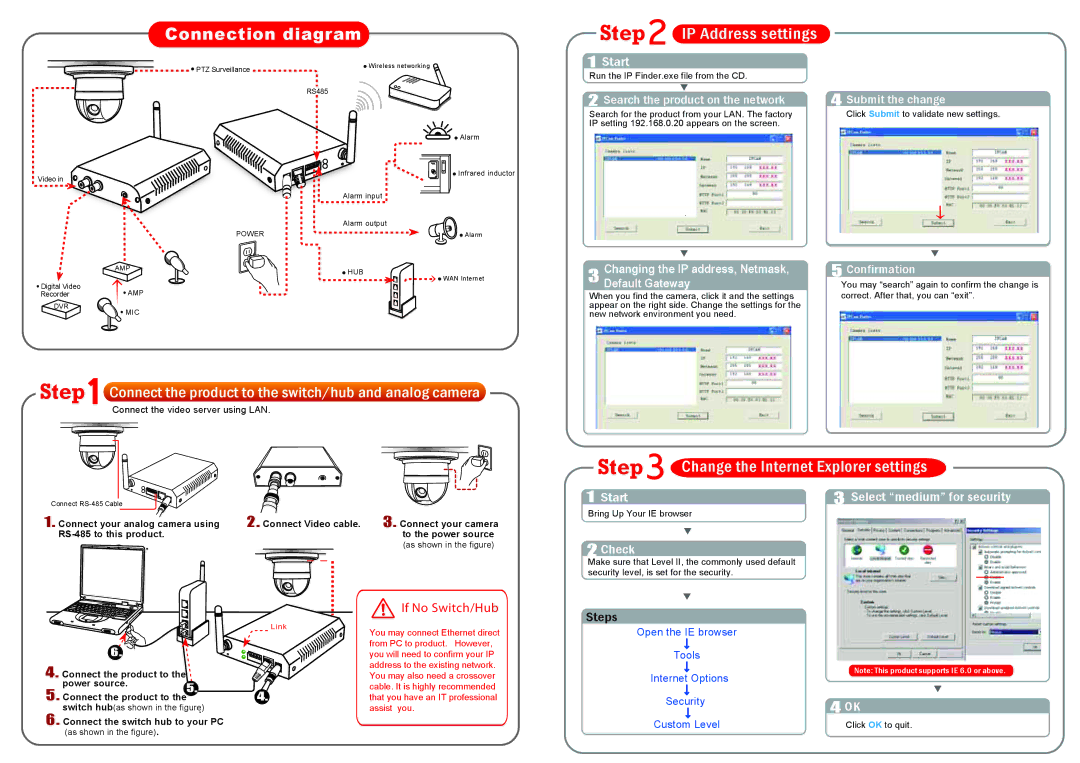
Video in
| Wireless networking | |
PTZ Surveillance | ||
|
RS485
Alarm input
Alarm output
POWER
![]() Alarm
Alarm
![]() Infrared inductor
Infrared inductor
![]() Alarm
Alarm
1Start
Run the IP Finder.exe file from the CD.
|
|
| ||
4 Submit the change | ||||
2 Search the product on the network | ||||
Search for the product from your LAN. The factory | 4 | Click Submit to validate new settings. | ||
IP setting 192.168.0.20 appears on the screen. |
| |||
.
AMP
![]() Digital Video
Digital Video
Recorder![]() AMP
AMP
DVR
![]() MIC
MIC
![]() HUB
HUB
![]()
![]() WAN Internet
WAN Internet
|
|
| |
Changing the IP address, Netmask, | |||
| 5 Confirmation | ||
3 Default Gateway |
|
| |
| 4You may “search” again to confirm the change is | ||
When you find the camera, click it and the settings |
| correct. After that, you can “exit”. | |
appear on the right side. Change the settings for the |
|
| |
new network environment you need. |
|
|
Step | Connect the product to the switch/hub and analog camera | ||
|
| Connect the video server using LAN. | |
|
|
|
|
Step |
|
|
Change the Internet Explorer settings | ||
|
|
|
Connect | bl | e |
|
|
|
1. Connect your analog camera using | 2. Connect Video cable. | ||||
|
|
| |||
|
|
|
|
|
|
3. Connect your camera to the power source
(as shown in the figure)
If No Switch/Hub
1Start
Bring Up Your IE browser
2Check
Make sure that Level II, the commonly used default security level, is set for the security.
Steps
3Select “medium” for security
6. ![]()
Link
You may connect Ethernet direct from PC to product. However, you will need to confirm your IP address to the existing network.
Open the IE browser
Tools
4. Connect the product to the |
|
power source. |
|
5. Connect the product to the5. | 4. |
6. switch hub(as shown in the figure).
You may also need a crossover cable. It is highly recommended that you have an IT professional assist you.
Internet Options
Note: This product supports IE 6.0 or above.
Security
4OK
Custom Level | Click OK to quit. |