Operating Manual -
9.Data Connections and Configurations
9.1 Standard Remote Data Control
To connect the
The Standard data protocol is compatible with cur- rent
Product
VCM-88
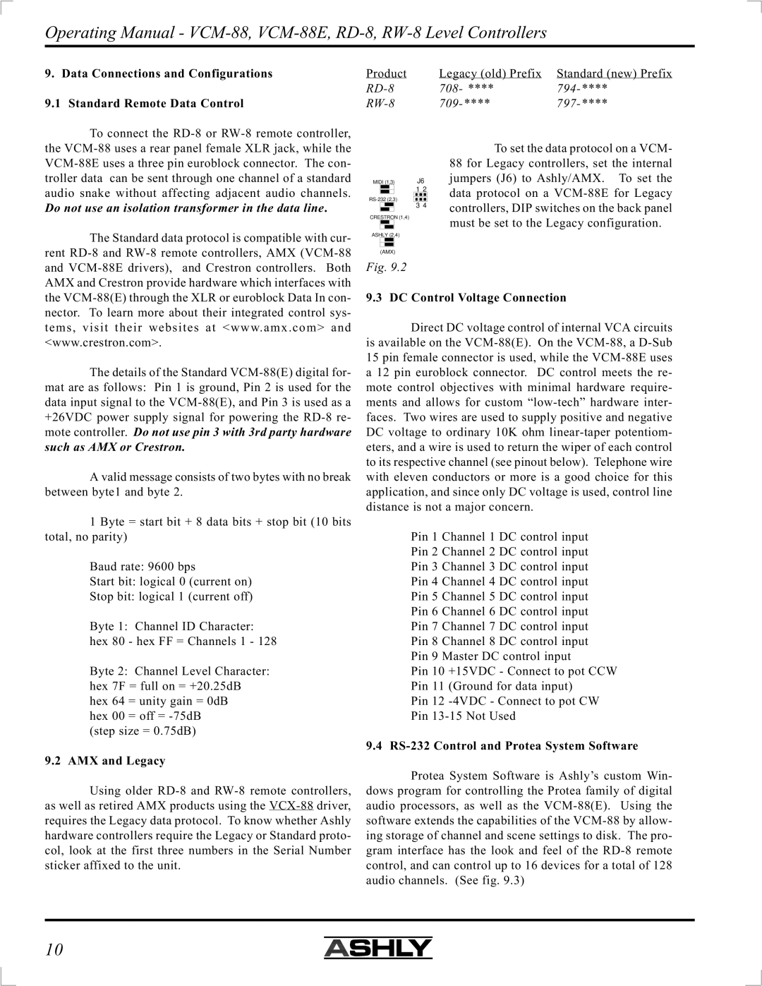
MIDI (1,3) | J6 | ||||||
|
|
|
|
| 1 2 | ||
|
|
| |||||
|
|
|
|
| 3 4 | ||
CRESTRON (1,4)
ASHLY (2,4)
(AMX)
Fig. 9.2
Legacy (old) Prefix | Standard (new) Prefix |
708- **** | |
To set the data protocol on a VCM- 88 for Legacy controllers, set the internal jumpers (J6) to Ashly/AMX. To set the data protocol on a
the
The details of the Standard
A valid message consists of two bytes with no break between byte1 and byte 2.
1 Byte = start bit + 8 data bits + stop bit (10 bits total, no parity)
Baud rate: 9600 bps
Start bit: logical 0 (current on)
Stop bit: logical 1 (current off)
Byte 1: Channel ID Character: hex 80 - hex FF = Channels 1 - 128
Byte 2: Channel Level Character: hex 7F = full on = +20.25dB hex 64 = unity gain = 0dB
hex 00 = off =
9.2 AMX and Legacy
Using older
9.3 DC Control Voltage Connection
Direct DC voltage control of internal VCA circuits is available on the
Pin 1 Channel 1 DC control input
Pin 2 Channel 2 DC control input
Pin 3 Channel 3 DC control input
Pin 4 Channel 4 DC control input
Pin 5 Channel 5 DC control input
Pin 6 Channel 6 DC control input
Pin 7 Channel 7 DC control input
Pin 8 Channel 8 DC control input
Pin 9 Master DC control input
Pin 10 +15VDC - Connect to pot CCW
Pin 11 (Ground for data input)
Pin 12
Pin
9.4
Protea System Software is Ashly’s custom Win- dows program for controlling the Protea family of digital audio processors, as well as the
10