Operating Manual -
8.Input and Output Configuration Options:
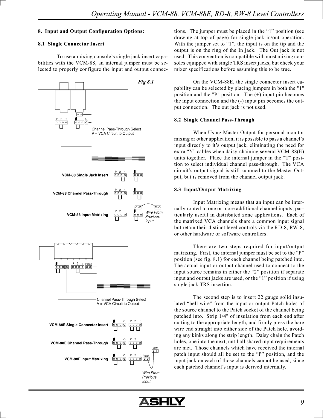
8.1 Single Connector Insert
To use a mixing console’s single jack insert capa- bilities with the
Fig 8.1
O
tions. The jumper must be placed in the “1” position (see drawing at top of page) for single jack in/out operation. With the jumper set to “1”, the input is on the tip and the output is on the ring of the In jack. The Out jack is not used. This convention is compatible with most mixing con- soles equipped with single TRS insert jacks, but check your mixer specifications before assuming this to be true.
On the
8.2 Single Channel
When Using Master Output for personal monitor mixing or other application, it is possible to pass a channel’s input directly to it’s output jack, eliminating the need for extra “Y” cables when
8.3 Input/Output Matrixing
Input Matrixing means that an input can be inter- nally routed to one or more additional channel inputs, par- ticularly useful in distributed zone applications. Each of the matrixed VCA channels share a common input signal but retain their distinct level controls via the
There are two steps required for input/output matrixing. First, the internal jumper must be set to the “P” position (see fig. 8.1) for each channel being patched into. The actual input or output channel used to connect to the input source remains in either the “2” position if separate input and output jacks are used, or the “1” position if using single jack TRS insertion.
The second step is to insert 22 gauge solid insu- lated “bell wire” from the input or output Patch holes of the source channel to the Patch socket of the channel being patched into. Strip 1/4" of insulation from each end after cutting to the appropriate length, and firmly press the bare wire end straight into either side of the Patch hole, avoid- ing any kinks along the strip length. Daisy chain the Patch holes, one into the next, until all shared input requirements are met. Those channels which have received the internal patch input should all be set to the “P” position, and the input jack on each of those channels cannot be used, since each patched channel’s input is derived internally.
9