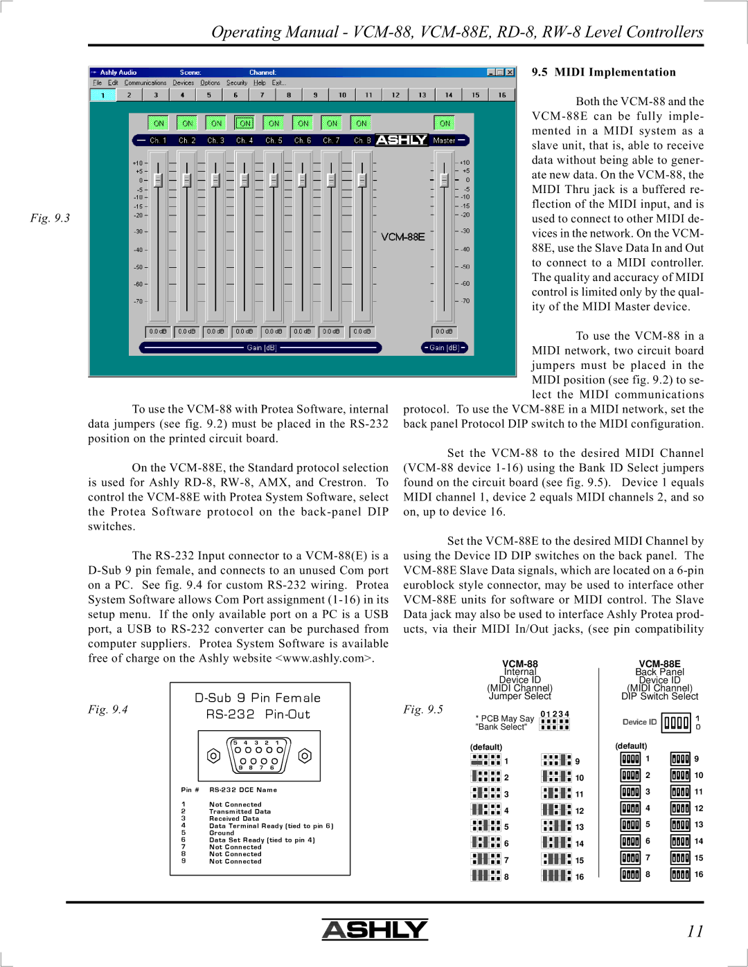
Fig. 9.3
To use the VCM-88 with Protea Software, internal data jumpers (see fig. 9.2) must be placed in the RS-232 position on the printed circuit board.
On the VCM-88E, the Standard protocol selection is used for Ashly RD-8, RW-8, AMX, and Crestron. To control the VCM-88E with Protea System Software, select the Protea Software protocol on the back-panel DIP switches.
The RS-232 Input connector to a VCM-88(E) is a D-Sub 9 pin female, and connects to an unused Com port on a PC. See fig. 9.4 for custom RS-232 wiring. Protea System Software allows Com Port assignment (1-16) in its setup menu. If the only available port on a PC is a USB port, a USB to RS-232 converter can be purchased from computer suppliers. Protea System Software is available free of charge on the Ashly website <www.ashly.com>.
D-Sub 9 Pin Female
Fig. 9.4 | RS-232 Pin-Out |
|
| 5 | 4 | 3 | 2 | 1 |
9 8 7 6
Pin # RS-232 DCE Name
1Not Connected
2Transmitted Data
3Received Data
4Data Terminal Ready (tied to pin 6)
5Ground
6Data Set Ready (tied to pin 4)
7Not Connected
8Not Connected
9Not Connected
9.5 MIDI Implementation
Both the VCM-88 and the VCM-88E can be fully imple- mented in a MIDI system as a slave unit, that is, able to receive data without being able to gener- ate new data. On the VCM-88, the MIDI Thru jack is a buffered re- flection of the MIDI input, and is used to connect to other MIDI de- vices in the network. On the VCM- 88E, use the Slave Data In and Out to connect to a MIDI controller. The quality and accuracy of MIDI control is limited only by the qual- ity of the MIDI Master device.
To use the VCM-88 in a MIDI network, two circuit board jumpers must be placed in the MIDI position (see fig. 9.2) to se- lect the MIDI communications
protocol. To use the VCM-88E in a MIDI network, set the back panel Protocol DIP switch to the MIDI configuration.
Set the VCM-88 to the desired MIDI Channel (VCM-88 device 1-16) using the Bank ID Select jumpers found on the circuit board (see fig. 9.5). Device 1 equals MIDI channel 1, device 2 equals MIDI channels 2, and so on, up to device 16.
Set the VCM-88E to the desired MIDI Channel by using the Device ID DIP switches on the back panel. The VCM-88E Slave Data signals, which are located on a 6-pin euroblock style connector, may be used to interface other VCM-88E units for software or MIDI control. The Slave Data jack may also be used to interface Ashly Protea prod- ucts, via their MIDI In/Out jacks, (see pin compatibility
VCM-88 | VCM-88E |
Internal | Back Panel |
Device ID | Device ID |
(MIDI Channel) | (MIDI Channel) |
Jumper Select | DIP Switch Select |
Fig. 9.5 | 0 | 1 | 2 3 4 |
* PCB May Say |
"Bank Select" | | | | | |
(default) | | (default) | |
1 | 9 | 1 | 9 |
2 | 10 | 2 | 10 |
3 | 11 | 3 | 11 |
4 | 12 | 4 | 12 |
5 | 13 | 5 | 13 |
6 | 14 | 6 | 14 |
7 | 15 | 7 | 15 |
8 | 16 | 8 | 16 |