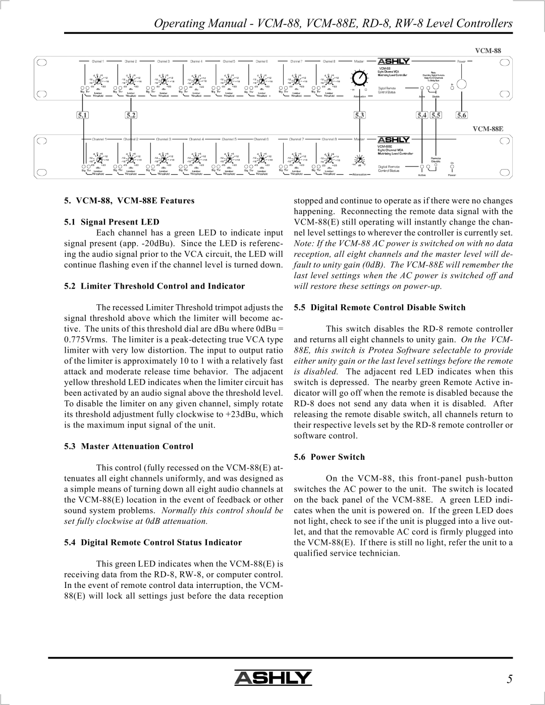
5. VCM-88, VCM-88E Features
5.1 Signal Present LED
Each channel has a green LED to indicate input signal present (app. -20dBu). Since the LED is referenc- ing the audio signal prior to the VCA circuit, the LED will continue flashing even if the channel level is turned down.
5.2 Limiter Threshold Control and Indicator
The recessed Limiter Threshold trimpot adjusts the signal threshold above which the limiter will become ac- tive. The units of this threshold dial are dBu where 0dBu = 0.775Vrms. The limiter is a peak-detecting true VCA type limiter with very low distortion. The input to output ratio of the limiter is approximately 10 to 1 with a relatively fast attack and moderate release time behavior. The adjacent yellow threshold LED indicates when the limiter circuit has been activated by an audio signal above the threshold level. To disable the limiter on any given channel, simply rotate its threshold adjustment fully clockwise to +23dBu, which is the maximum input signal of the unit.
5.3 Master Attenuation Control
This control (fully recessed on the VCM-88(E) at- tenuates all eight channels uniformly, and was designed as a simple means of turning down all eight audio channels at the VCM-88(E) location in the event of feedback or other sound system problems. Normally this control should be set fully clockwise at 0dB attenuation.
5.4 Digital Remote Control Status Indicator
This green LED indicates when the VCM-88(E) is receiving data from the RD-8, RW-8, or computer control. In the event of remote control data interruption, the VCM- 88(E) will lock all settings just before the data reception
stopped and continue to operate as if there were no changes happening. Reconnecting the remote data signal with the VCM-88(E) still operating will instantly change the chan- nel level settings to wherever the controller is currently set. Note: If the VCM-88 AC power is switched on with no data reception, all eight channels and the master level will de- fault to unity gain (0dB). The VCM-88E will remember the last level settings when the AC power is switched off and will restore these settings on power-up.
5.5 Digital Remote Control Disable Switch
This switch disables the RD-8 remote controller and returns all eight channels to unity gain. On the VCM- 88E, this switch is Protea Software selectable to provide either unity gain or the last level settings before the remote is disabled. The adjacent red LED indicates when this switch is depressed. The nearby green Remote Active in- dicator will go off when the remote is disabled because the RD-8 does not send any data when it is disabled. After releasing the remote disable switch, all channels return to their respective levels set by the RD-8 remote controller or software control.
5.6 Power Switch
On the VCM-88, this front-panel push-button switches the AC power to the unit. The switch is located on the back panel of the VCM-88E. A green LED indi- cates when the unit is powered on. If the green LED does not light, check to see if the unit is plugged into a live out- let, and that the removable AC cord is firmly plugged into the VCM-88(E). If there is still no light, refer the unit to a qualified service technician.