Ashly manual Operating Manual - VCM-88, VCM-88E, RD-8, RW-8 Level Controllers

Models: VCM-88E VCM-88

1 20
Download 20 pages 19.34 Kb
Page 8
Image 8
7. Audio Connections and Cables

Operating Manual - VCM-88, VCM-88E, RD-8, RW-8 Level Controllers

7. Audio Connections and Cables

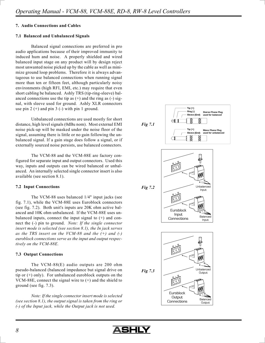
7.1 Balanced and Unbalanced Signals

Balanced signal connections are preferred in pro audio applications because of their improved immunity to induced hum and noise. A properly shielded and wired balanced input stage on any product will by design reject most unwanted noise picked up by the cable as well as mini- mize ground loop problems. Therefore it is always advan- tageous to use balanced connections when running signal more than ten or fifteen feet, although particularly noisy environments (high RFI, EMI, etc.) may require that even short cabling be balanced. Ashly TRS (tip-ring-sleeve) bal- anced connections use the tip as (+) and the ring as (-) sig- nal, with sleeve used for ground. Ashly XLR connectors use pin 2 (+) and pin 3 (-) with pin 1 ground.

Unbalanced connections are used mostly for short distance, high level signals (0dBu nom). Most external EMI noise pick-up will be masked under the noise floor of the signal, assuming there is little or no gain following the un- balanced signal. If a gain stage does follow a signal, or if externally sourced noise persists, use balanced connectors.

The VCM-88 and the VCM-88E are factory con- figured for separate input and output connectors. Used this way, inputs and outputs can be wired balanced or unbal- anced. An internally selected single connector insert is also available (see section 8.1).

7.2 Input Connections

The VCM-88 uses balanced 1/4" input jacks (see fig. 7.1), while the VCM-88E uses Euroblock connectors (see fig. 7.2). Both unit's inputs are 20K ohm active bal- anced and 10K ohm unbalanced. If the VCM-88E uses un- balanced inputs, connect the input signal to (+) and con- nect the (-) pin to ground. Note: If the single connector insert mode is selected (see section 8.1), the In jack serves as the TRS insert on the VCM-88 and the (+) and (-) euroblock connections serve as the input and output respec-

Fig 7.1

Fig 7.2

Tip (+)


Ring (-)

Stereo Phone Plug

Sleeve (Gnd)

used for balanced


Tip (+)

Mono Phone Plug

Sleeve (Gnd)

used for unbalanced


+ - GManual background

+ - GManual background

Unbalanced

Input

+- G Manual background

Euroblock + - G

Input

Balanced

Connections Input

tively on the VCM-88E.

7.3 Output Connections

The VCM-88(E) audio outputs are 200 ohm

+ - GManual background

+

G

pseudo-balanced (balanced impedance but signal drive on tip or (+) only). For unbalanced euroblock outputs on the VCM-88E, connect the signal wire to (+) and the shield to ground (see fig. 7.3).

Note: If the single connector insert mode is selected (see section 8.1), the output signal is taken from the ring or (-) of the Input jack, while the Output jack is not used.

Fig 7.3

Unbalanced

Output

+- G Manual background

Euroblock + - G Output Manual backgroundManual background

Balanced

Connections Output

8

Page 8
Image 8
Ashly manual Operating Manual - VCM-88, VCM-88E, RD-8, RW-8 Level Controllers