2.7 Jumpers Setup
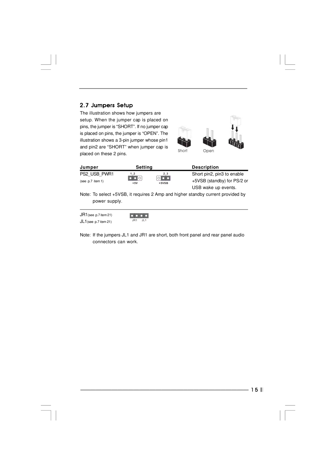
The illustration shows how jumpers are setup. When the jumper cap is placed on pins, the jumper is “SHORT”. If no jumper cap is placed on pins, the jumper is “OPEN”. The illustration shows a
Jumper | Setting |
| Description |
PS2_USB_PWR1 | 1_2 | 2_3 | Short pin2, pin3 to enable |
|
| ||
(see p.7 item 1) | +5V | +5VSB | +5VSB (standby) for PS/2 or |
|
|
USB wake up events.
Note: To select +5VSB, it requires 2 Amp and higher standby current provided by power supply.
JR1(see p.7 item 21)
JL1(see p.7 item 21) | JR1 JL1 |
|
Note: If the jumpers JL1 and JR1 are short, both front panel and rear panel audio connectors can work.
1 5