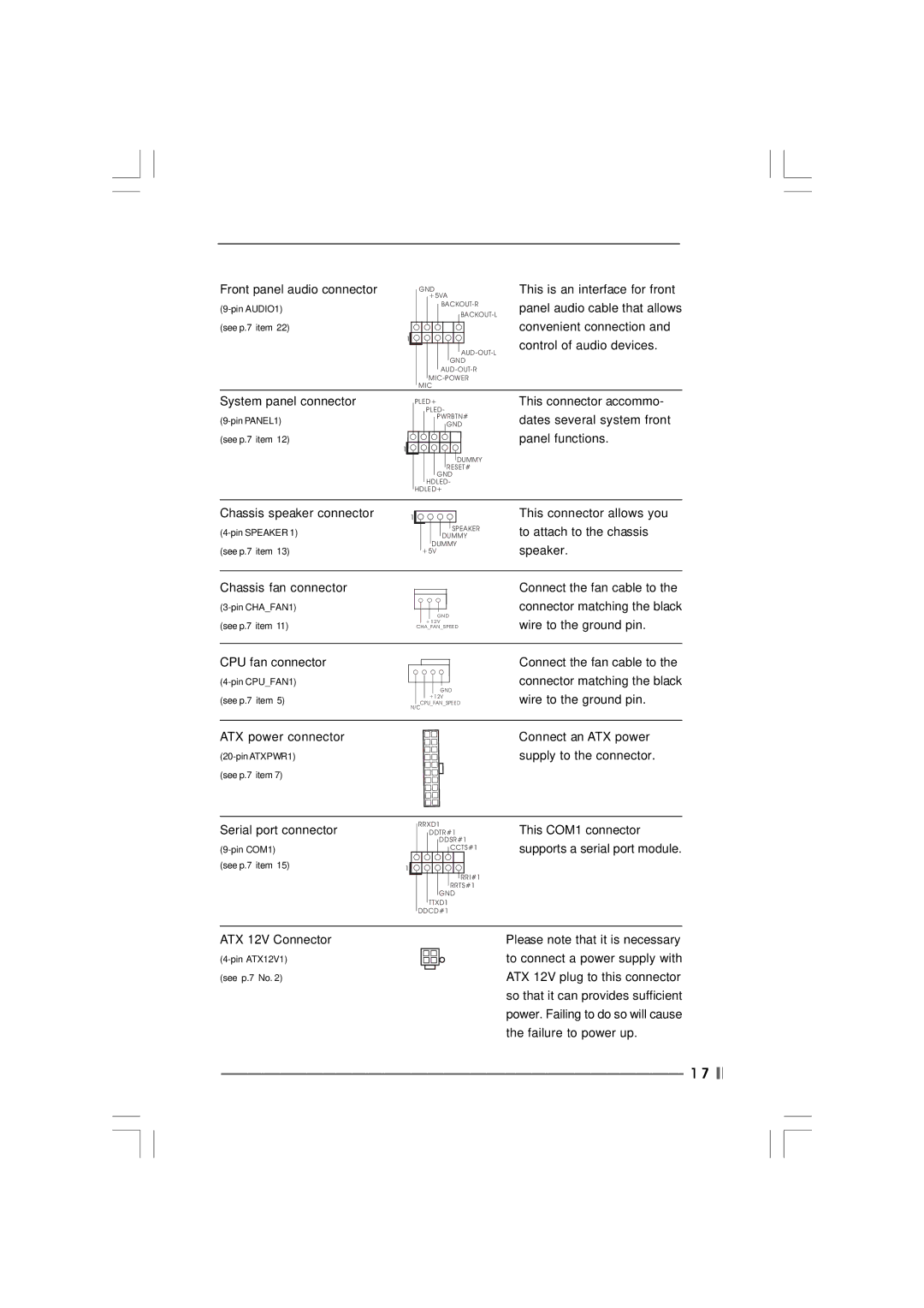
Front panel audio connector |
|
| GND | ||||||||||
|
|
|
|
| +5VA | ||||||||
|
|
|
|
|
| ||||||||
|
|
|
|
|
|
|
|
|
|
| |||
(see p.7 item 22) |
|
|
|
|
|
|
|
|
|
|
|
|
|
| 1 |
|
|
|
|
|
|
|
|
|
|
|
|
|
|
|
|
|
|
|
|
|
|
|
| ||
|
|
|
|
|
|
|
|
|
|
| |||
|
|
|
|
|
|
|
|
| GND | ||||
|
|
|
|
|
|
| |||||||
|
|
|
|
|
|
| |||||||
|
|
|
|
| |||||||||
|
|
|
|
| |||||||||
|
|
| MIC | ||||||||||
This is an interface for front panel audio cable that allows convenient connection and control of audio devices.
System panel connector
(see p.7 item 12)
1
PLED+
PLED-
PWRBTN#
GND
DUMMY RESET#
GND HDLED-
HDLED+
This connector accommo- dates several system front panel functions.
Chassis speaker connector |
|
1 |
SPEAKER DUMMY
DUMMY +5V
This connector allows you to attach to the chassis speaker.
Chassis fan connector
(see p.7 item 11)
GND
+12V
CHA_FAN_SPEED
Connect the fan cable to the connector matching the black wire to the ground pin.
CPU fan connector
(see p.7 item 5)
GND
+12V
CPU_FAN_SPEED N/C
Connect the fan cable to the connector matching the black wire to the ground pin.
ATX power connector | Connect an ATX power |
supply to the connector. | |
(see p.7 item 7) |
|
Serial port connector
| |
(see p.7 item 15) | 1 |
RRXD1
DDTR#1 DDSR#1
CCTS#1
RRI#1
RRTS#1
GND
TTXD1
DDCD#1
This COM1 connector supports a serial port module.
ATX 12V Connector
(see p.7 No. 2)
Please note that it is necessary to connect a power supply with ATX 12V plug to this connector so that it can provides sufficient power. Failing to do so will cause the failure to power up.
1 7