2.8 Onboard Headers and Connectors
Connectors are NOT jumpers. DO NOT place jumper caps over these connectors.
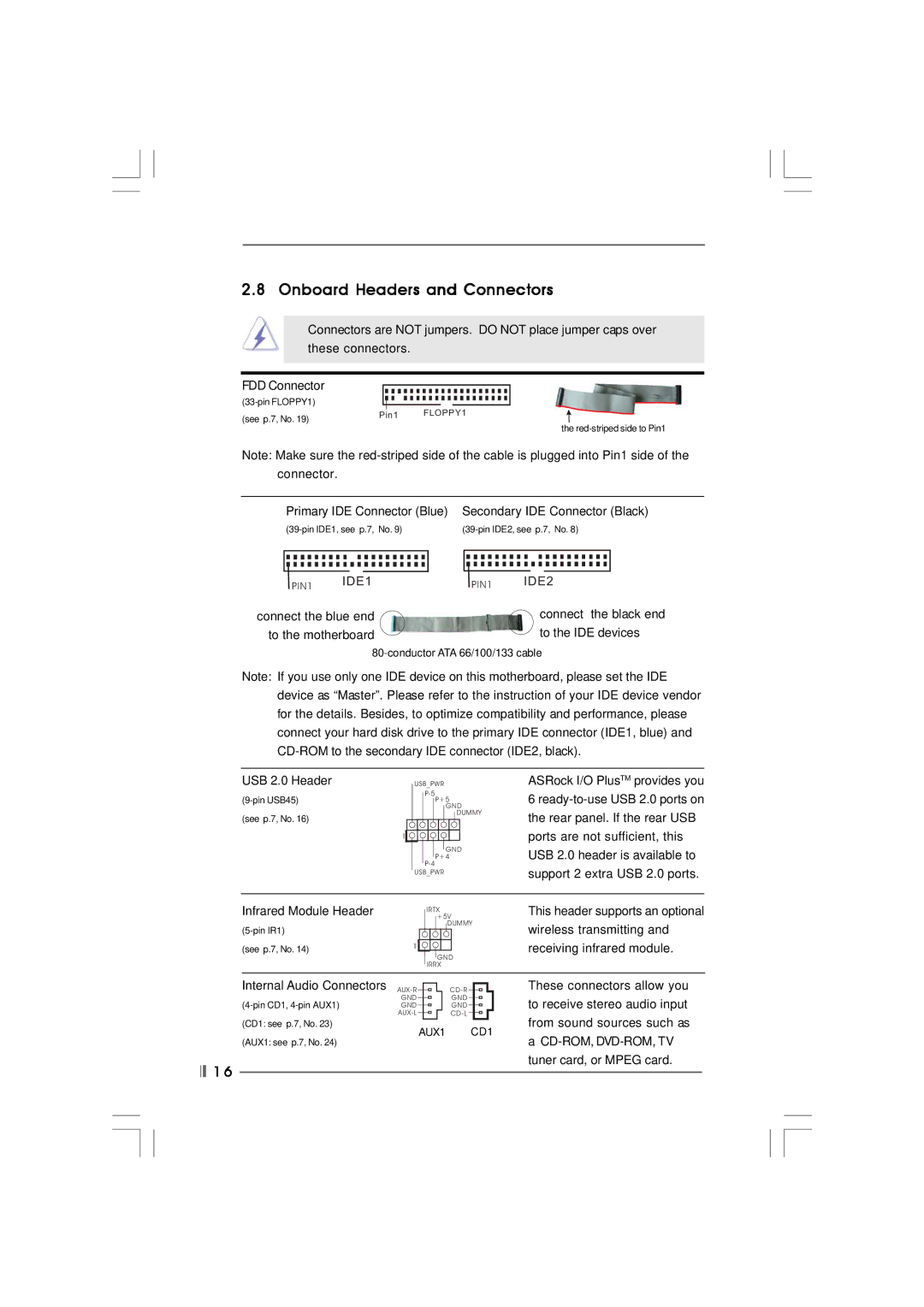
FDD Connector
(see p.7, No. 19) | Pin1 | FLOPPY1 |
| ||
|
|
the
Note: Make sure the
| Primary IDE Connector (Blue) | Secondary IDE Connector (Black) | ||||||||
| ||||||||||
|
|
|
|
|
|
|
|
|
|
|
|
|
|
|
|
|
|
|
|
|
|
| PIN1 | IDE1 | PIN1 | IDE2 | ||||||
|
|
|
|
|
|
|
|
| ||
connect the blue end |
|
| connect the black end | |||||||
to the motherboard |
|
| to the IDE devices | |||||||
Note: If you use only one IDE device on this motherboard, please set the IDE device as “Master”. Please refer to the instruction of your IDE device vendor for the details. Besides, to optimize compatibility and performance, please connect your hard disk drive to the primary IDE connector (IDE1, blue) and
USB 2.0 Header | USB_PWR |
P+5 | |
| GND |
(see p.7, No. 16) | DUMMY |
| |
| 1 |
| GND |
| P+4 |
| |
| USB_PWR |
ASRock I/O PlusTM provides you 6
Infrared Module Header
(see p.7, No. 14) | 1 |
|
IRTX +5V
DUMMY
GND
IRRX
This header supports an optional wireless transmitting and receiving infrared module.
Internal Audio Connectors
(CD1: see p.7, No. 23)
(AUX1: see p.7, No. 24)
![]()
![]() 1 6
1 6
GND | GND |
GND | GND |
AUX1 CD1
These connectors allow you to receive stereo audio input from sound sources such as
a