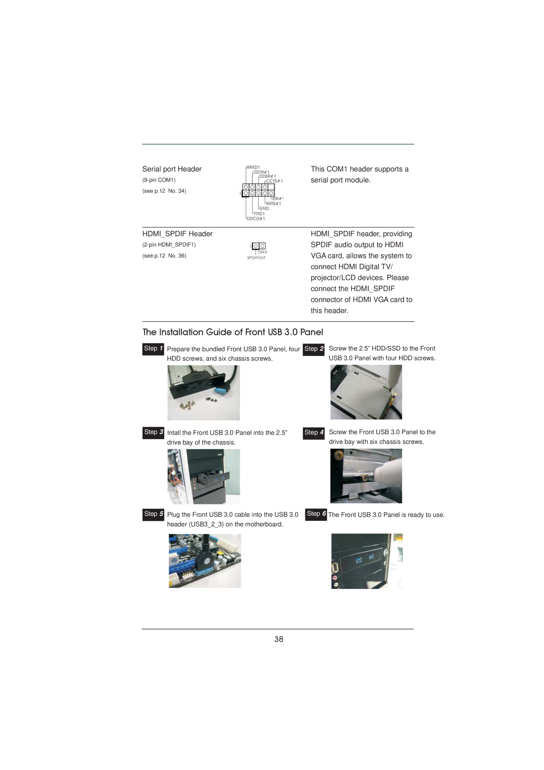
Serial port Header | This COM1 header supports a |
serial port module. | |
(see p.12 No. 34) |
|
HDMI_SPDIF Header
(see p.12 No. 36)
1 |
GND
SPDIFOUT
HDMI_SPDIF header, providing SPDIF audio output to HDMI VGA card, allows the system to connect HDMI Digital TV/ projector/LCD devices. Please connect the HDMI_SPDIF connector of HDMI VGA card to this header.
The Installation Guide of Front USB 3.0 Panel
Step 1 Prepare the bundled Front USB 3.0 Panel, four Step 2 HDD screws, and six chassis screws.
Screw the 2.5” HDD/SSD to the Front USB 3.0 Panel with four HDD screws.
Step 3
Intall the Front USB 3.0 Panel into the 2.5” drive bay of the chassis.
Step 4
Screw the Front USB 3.0 Panel to the drive bay with six chassis screws.
Step 5
Plug the Front USB 3.0 cable into the USB 3.0 header (USB3_2_3) on the motherboard.
Step 6
The Front USB 3.0 Panel is ready to use.
38