The Installation Guide of Rear USB 3.0 Bracket
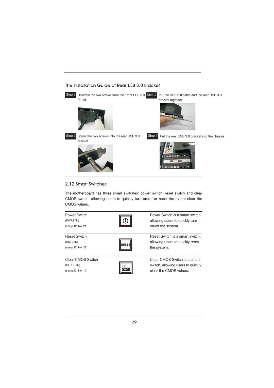
Step 1
Unscrew the two screws from the Front USB 3.0 Step 2 Panel.
Put the USB 3.0 cable and the rear USB 3.0 bracket together.
Step 3
Screw the two screws into the rear USB 3.0 bracket.
Step 4
Put the rear USB 3.0 bracket into the chassis.
2.12 Smart Switches
The motherboard has three smart switches: power switch, reset switch and clear CMOS switch, allowing users to quickly turn on/off or reset the sytem clear the CMOS values.
Power Switch
(PWRBTN)
(see p.12 No. 21)
Power Switch is a smart switch, allowing users to quickly turn on/off the system.
Reset Switch
(RSTBTN)
(see p.12 No. 22)
RESET
Reset Switch is a smart switch, allowing users to quickly reset the system.
Clear CMOS Switch
(CLRCBTN)
(see p.13 No. 17)
clr
CMOS
Clear CMOS Switch is a smart switch, allowing users to quickly clear the CMOS values.
39