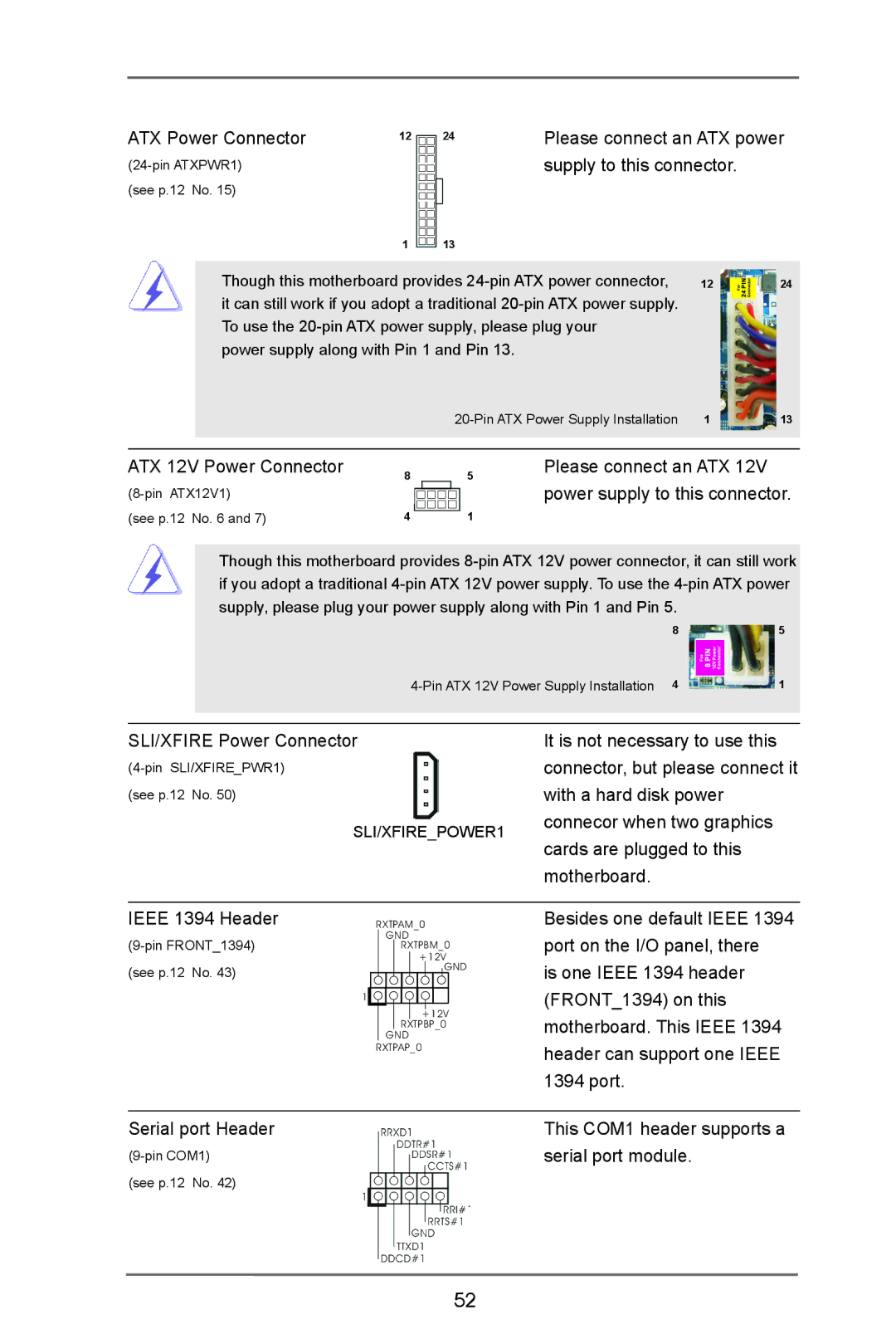
ATX Power Connector | 12 24 |
(see p.12 No. 15)
1 13
Please connect an ATX power supply to this connector.
| Though this motherboard provides | 12 |
| 24 |
|
| |||
| it can still work if you adopt a traditional |
|
|
|
| To use the |
|
|
|
| power supply along with Pin 1 and Pin 13. |
|
|
|
| 1 | 13 | ||
|
|
|
|
|
|
|
|
|
|
ATX 12V Power Connector | 8 | 5 |
| ||
|
| |
(see p.12 No. 6 and 7) | 4 | 1 |
Please connect an ATX 12V power supply to this connector.
Though this motherboard provides
85
1 |
SLI/XFIRE Power Connector
(see p.12 No. 50)
SLI/XFIRE_POWER1
It is not necessary to use this connector, but please connect it with a hard disk power connecor when two graphics cards are plugged to this motherboard.
IEEE 1394 Header | RXTPAM_0 |
GND | |
RXTPBM_0 | |
| +12V |
(see p.12 No. 43) | GND |
| |
| 1 |
| +12V |
| RXTPBP_0 |
| GND |
| RXTPAP_0 |
Besides one default IEEE 1394 port on the I/O panel, there
is one IEEE 1394 header (FRONT_1394) on this motherboard. This IEEE 1394 header can support one IEEE 1394 port.
Serial port Header | This COM1 header supports a |
serial port module. | |
(see p.12 No. 42) |
|
52