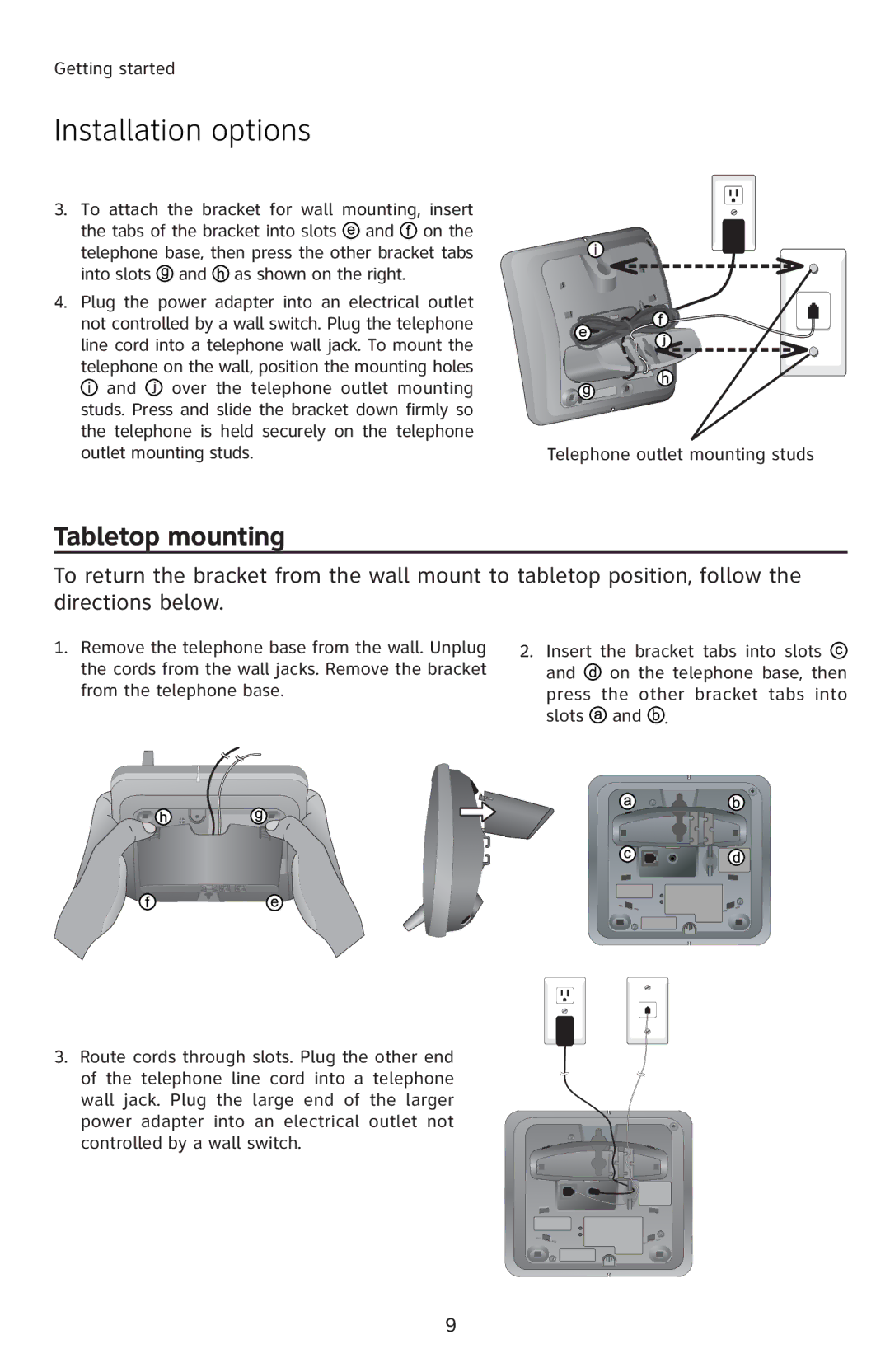
E1814B, E5812B, E5813B, E5814B, E1812B specifications
AT&T has consistently been a leading provider in the telecommunications market, and its recent offerings, including the AT&T E1813B, E1812B, E5814B, E5813B, and E5812B, showcase the latest advancements in mobile communication technology. These devices are designed to meet diverse user needs, from enhanced connectivity to robust performance.The AT&T E1813B stands out with its impressive battery life, allowing users to stay connected for extended periods without frequent recharging. It supports various network technologies, ensuring seamless communication whether users are streaming media, participating in video calls, or browsing the internet. With a user-friendly interface, the E1813B is ideal for both tech-savvy consumers and those new to smart devices.
Similarly, the AT&T E1812B brings forward an ergonomic design paired with advanced features. This device is particularly noted for its enhanced audio quality, making it a solid choice for users who prioritize voice clarity during calls. The E1812B also includes built-in security features to protect user data, catering to the needs of privacy-conscious individuals.
Moving to the E5814B, this model targets users who demand versatility in their mobile devices. Equipped with dual-SIM capabilities, it allows users to manage multiple lines efficiently, whether for business or personal use. Additionally, the E5814B supports 4G LTE connectivity, providing users with high-speed internet access for both work and entertainment.
The E5813B, on the other hand, focuses on connectivity and smart features. It includes Wi-Fi calling and the latest Bluetooth technology, enabling users to connect to different devices effortlessly. Its compatibility with various smart home devices adds to its appeal for modern users looking to integrate their digital ecosystems.
Finally, the AT&T E5812B offers a balanced mix of practicality and advanced features. With a sleek design and a variety of color options, it appeals to a broader audience. The E5812B is equipped with a powerful processor, ensuring smooth multitasking and application performance, ideal for those who juggle multiple tasks throughout their day.
In summary, the AT&T E1813B, E1812B, E5814B, E5813B, and E5812B present a variety of options for consumers seeking reliable and feature-rich mobile devices. With their emphasis on connectivity, security, and user-friendly designs, these devices effectively cater to the evolving demands of today's mobile users. Whether for professional use or personal enjoyment, these models stand as testament to AT&T's commitment to innovation in telecommunications.

