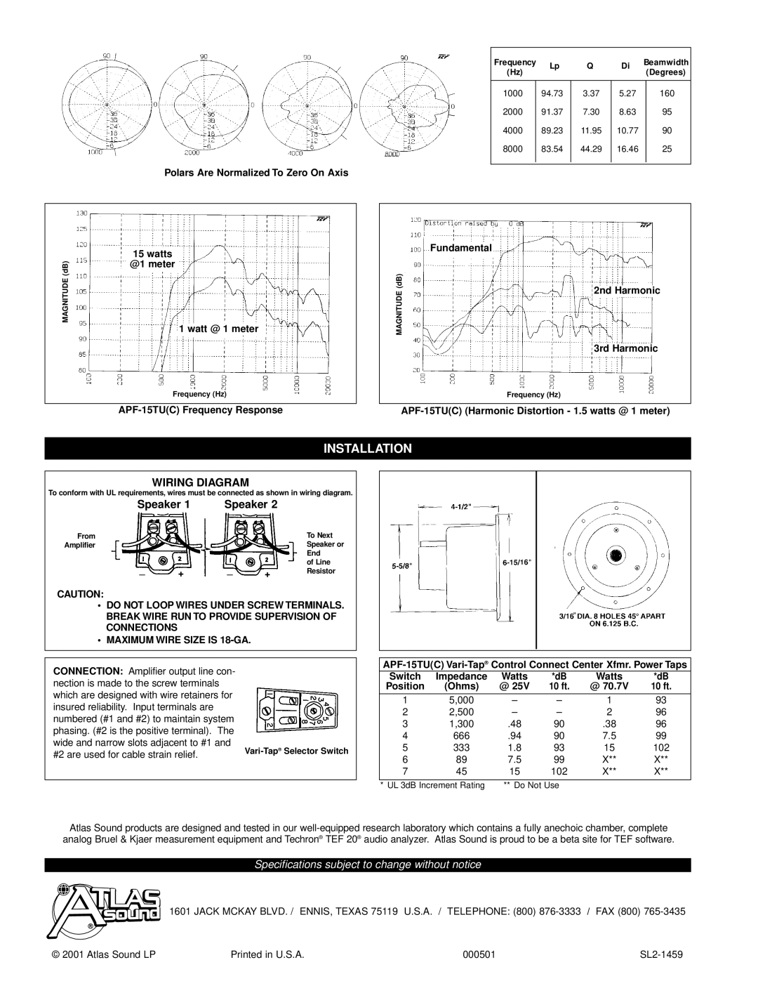
MAGNITUDE (dB)
Polars Are Normalized To Zero On Axis
15watts @1 meter
1 watt @ 1 meter
Frequency (Hz)
APF-15TU(C) Frequency Response
Frequency | Lp | Q | Di | Beamwidth | |
(Hz) |
| (Degrees) | |||
|
|
|
| ||
|
|
|
|
|
|
1000 | 94.73 | 3.37 | 5.27 |
| 160 |
2000 | 91.37 | 7.30 | 8.63 |
| 95 |
4000 | 89.23 | 11.95 | 10.77 |
| 90 |
8000 | 83.54 | 44.29 | 16.46 |
| 25 |
|
|
|
|
|
|
Fundamental
(dB) |
|
| |
2nd Harmonic | |||
MAGNITUDE |
| ||
|
| ||
|
|
|
3rd Harmonic
Frequency (Hz)
INSTALLATION
WIRING DIAGRAM
To conform with UL requirements, wires must be connected as shown in wiring diagram.
| Speaker 1 | Speaker 2 |
| ||
From |
|
|
|
| To Next |
Amplifier |
|
|
|
| Speaker or |
|
|
|
|
| End |
| _ |
| _ |
| of Line |
| + | + | Resistor | ||
|
|
|
| ||
|
|
|
|
|
|
CAUTION:
•DO NOT LOOP WIRES UNDER SCREW TERMINALS. BREAK WIRE RUN TO PROVIDE SUPERVISION OF CONNECTIONS
•MAXIMUM WIRE SIZE IS
CONNECTION: Amplifier output line con- nection is made to the screw terminals which are designed with wire retainers for insured reliability. Input terminals are numbered (#1 and #2) to maintain system phasing. (#2 is the positive terminal). The wide and narrow slots adjacent to #1 and
#2 are used for cable strain relief. | Selector Switch | |
|
|
Switch | Impedance | Watts | *dB | Watts | *dB |
Position | (Ohms) | @ 25V | 10 ft. | @ 70.7V | 10 ft. |
1 | 5,000 | – | – | 1 | 93 |
2 | 2,500 | – | – | 2 | 96 |
3 | 1,300 | .48 | 90 | .38 | 96 |
4 | 666 | .94 | 90 | 7.5 | 99 |
5 | 333 | 1.8 | 93 | 15 | 102 |
6 | 89 | 7.5 | 99 | X** | X** |
7 | 45 | 15 | 102 | X** | X** |
* UL 3dB Increment Rating | ** Do Not Use |
Atlas Sound products are designed and tested in our
Specifications subject to change without notice
1601 JACK MCKAY BLVD. / ENNIS, TEXAS 75119 U.S.A. / TELEPHONE: (800)
© 2001 Atlas Sound LP | Printed in U.S.A. | 000501 |
