4.0 EXPLODED ASSEMBLY DIAGRAMS
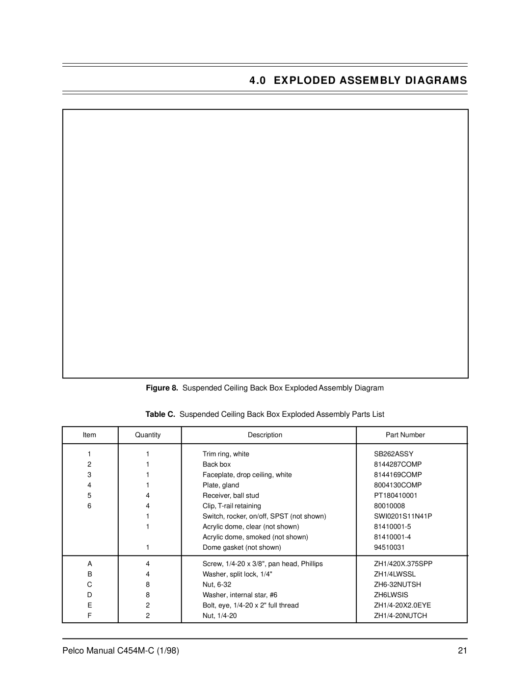
Figure 8. Suspended Ceiling Back Box Exploded Assembly Diagram
Table C. Suspended Ceiling Back Box Exploded Assembly Parts List
Item | Quantity | Description | Part Number |
|
|
|
|
|
|
1 | 1 | Trim ring, white | SB262ASSY |
|
2 | 1 | Back box | 8144287COMP |
|
3 | 1 | Faceplate, drop ceiling, white | 8144169COMP |
|
4 | 1 | Plate, gland | 8004130COMP |
|
5 | 4 | Receiver, ball stud | PT180410001 |
|
6 | 4 | Clip, | 80010008 |
|
| 1 | Switch, rocker, on/off, SPST (not shown) | SWI0201S11N41P |
|
| 1 | Acrylic dome, clear (not shown) |
| |
|
| Acrylic dome, smoked (not shown) |
| |
| 1 | Dome gasket (not shown) | 94510031 |
|
|
|
|
|
|
A | 4 | Screw, | ZH1/420X.375SPP |
|
B | 4 | Washer, split lock, 1/4" | ZH1/4LWSSL |
|
C | 8 | Nut, |
| |
D | 8 | Washer, internal star, #6 | ZH6LWSIS |
|
E | 2 | Bolt, eye, |
| |
F | 2 | Nut, |
| |
|
|
|
|
|
Pelco Manual | 21 |