Series 1500 specifications
The Audio Authority Series 1500 is a premier line of audio/video distribution solutions designed to meet the complexities of modern audio setups. This series demonstrates a commitment to quality, efficiency, and ease of use, catering to both professional audio engineers and home entertainment enthusiasts.One of the standout features of the Series 1500 is its versatile distribution capabilities. It supports a wide range of audio formats and offers multiple output options, making it suitable for both analog and digital audio setups. The series is equipped with cutting-edge technologies that allow for seamless switching and distribution, ensuring that users experience crystal-clear audio across various devices.
The Series 1500 utilizes advanced signal processing technology, which helps maintain audio integrity and reduces noise interference. This is particularly important in complex installations where long cable runs can lead to signal loss. The equipment has been designed to handle multiple input sources, allowing users to switch effortlessly between devices, whether it’s a CD player, streaming box, or computer.
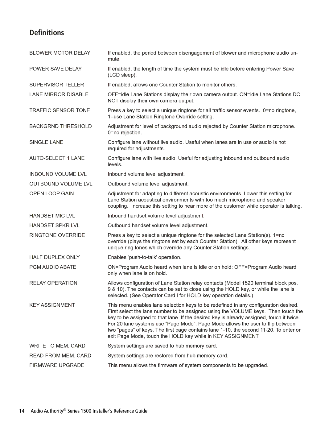
Another important characteristic of the Audio Authority Series 1500 is its user-friendly interface. The series typically features easy-to-read displays and intuitive controls that make setup and operation straightforward, even for those who are not technically inclined. In addition, the products are designed with robust construction, ensuring durability and reliability in both residential and commercial environments.
Moreover, the Series 1500 supports a range of connectivity options, including HDMI, RCA, and optical connections, making it highly adaptable to various audio/video configurations. This flexibility is essential for installations that may need to accommodate different types of equipment over time.
Lastly, the Audio Authority Series 1500 is known for its scalability, allowing users to expand their audio distribution system as needed. Whether adding more zones in a home or scaling up for a larger commercial installation, the Series 1500 can grow alongside user requirements.
In summary, the Audio Authority Series 1500 stands out as a versatile and reliable choice for audio distribution. With its advanced technologies, user-friendly interface, and robust construction, it caters to the diverse needs of modern audio installations, positioning it as a top contender in the audio distribution market.
