
LRX 4.300 specifications
The Audison LRX 4.300 is a powerful and versatile four-channel amplifier designed for high-performance car audio systems. Its robust build and advanced technologies make it a favorite among audiophiles looking to elevate their listening experience on the road.One of the standout features of the LRX 4.300 is its superior power output. Delivering an impressive 4 x 75 Watts RMS at 4 ohms, this amplifier is capable of driving the most demanding speakers while maintaining clarity and dynamic range. Whether you're powering a full range of components or simply looking to enhance your existing setup, the LRX 4.300 delivers ample power along with exceptional sound quality.
The amplifier incorporates Class AB technology, which is known for offering a warm and detailed sound. This class combines the efficiency of Class D with the high fidelity of traditional Class A amplifiers, resulting in low distortion and high linearity. This means that whether you're listening to soft jazz or heavy metal, the LRX 4.300 preserves the nuances, ensuring a rich listening experience.
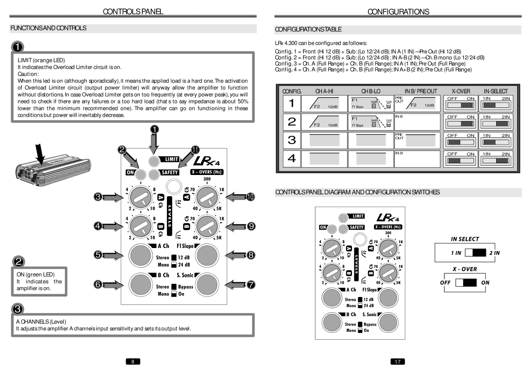
Another notable feature is its flexibility in channel configuration. The LRX 4.300 can be used in various setups: as a full four-channel amplifier, or two channels driving high-frequency components while bridging the other two channels for use with a subwoofer. This versatility allows users to customize their systems based on individual preferences and requirements.
Advanced technologies also play a significant role in this amplifier's performance. The built-in crossover system offers both high-pass and low-pass filters that enable precise tuning of each driver. This ensures that each component receives the right frequencies, optimizing overall sound quality and avoiding distortion.
Additionally, the LRX 4.300 features an impressive signal-to-noise ratio, which helps to minimize unwanted noise, further enhancing the clarity of the audio. Its compact design allows for easy installation in various vehicle types, without compromising on available space.
In conclusion, the Audison LRX 4.300 stands out in the competitive car amplifier market due to its powerful output, excellent sound quality, and versatile configurations. Whether for casual listening or serious sound enthusiasts, this amplifier meets the demands of any audio system, ensuring an immersive sound experience on the go.