G
Fig. 5.6
Do not use this step |
Safety |
catch |
Fig. 5.7 |
Fig. 5.8 |
OVEN ACCESSORIES INSTALLATION AND REMOVAL
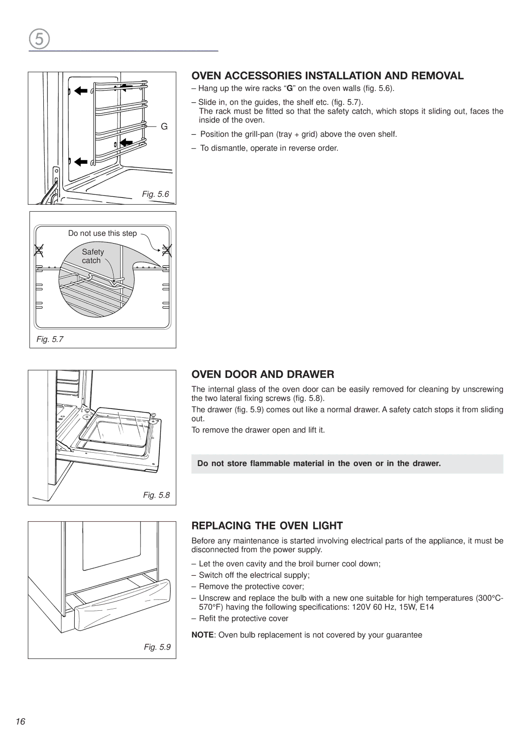
–Hang up the wire racks “G” on the oven walls (fig. 5.6).
–Slide in, on the guides, the shelf etc. (fig. 5.7).
The rack must be fitted so that the safety catch, which stops it sliding out, faces the inside of the oven.
–Position the
–To dismantle, operate in reverse order.
OVEN DOOR AND DRAWER
The internal glass of the oven door can be easily removed for cleaning by unscrewing the two lateral fixing screws (fig. 5.8).
The drawer (fig. 5.9) comes out like a normal drawer. A safety catch stops it from sliding out.
To remove the drawer open and lift it.
Do not store flammable material in the oven or in the drawer.
Fig. 5.9 |
REPLACING THE OVEN LIGHT
Before any maintenance is started involving electrical parts of the appliance, it must be disconnected from the power supply.
–Let the oven cavity and the broil burner cool down;
–Switch off the electrical supply;
–Remove the protective cover;
–Unscrew and replace the bulb with a new one suitable for high temperatures (300°C- 570°F) having the following specifications: 120V 60 Hz, 15W, E14
–Refit the protective cover
NOTE: Oven bulb replacement is not covered by your guarantee
16
