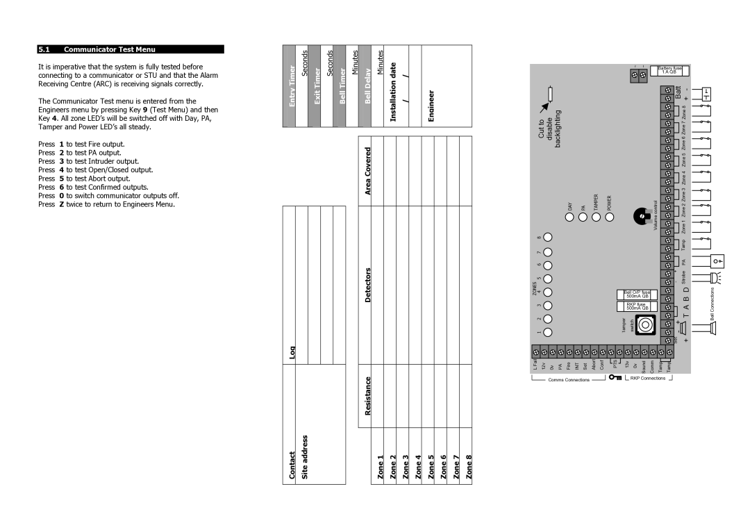
5.1Communicator Test Menu
It is imperative that the system is fully tested before connecting to a communicator or STU and that the Alarm Receiving Centre (ARC) is receiving signals correctly.
|
|
|
|
| Minutes | Delay | Minutes | date | / |
|
|
|
|
| |
|
|
|
|
|
|
|
|
|
|
|
|
|
|
|
|
|
|
|
|
|
|
|
|
|
|
|
|
|
|
|
|
|
|
|
|
|
|
|
|
|
|
|
|
|
|
|
|
|
|
|
|
|
|
|
|
|
|
|
|
|
|
|
|
|
|
|
|
|
|
|
|
|
|
|
|
|
|
|
|
|
|
|
|
|
|
|
|
|
|
|
|
|
|
|
|
~ ~ | Battery fuse |
| |
| 1.A QB |
The Communicator Test menu is entered from the Engineers menu by pressing Key 9 (Test Menu) and then Key 4. All zone LED’s will be switched off with Day, PA, Tamper and Power LED’s all steady.
Press | 1 to test Fire output. |
Press | 2 to test PA output. |
Press | 3 to test Intruder output. |
Press | 4 to test Open/Closed output. |
Press | 5 to test Abort output. |
Press | 6 to test Confirmed outputs. |
Press | 0 to switch communicator outputs off. |
Press | Z twice to return to Engineers Menu. |
Bell | Installation | / | Engineer |
Area Covered |
|
|
|
Detectors
Cut to disable backlighting
DAY | PA | TAMPER | POWER |
ZONES 1 2 3 4 5 6 7 8![]()
![]()
![]() Volume control
Volume control
Bell O/P fuse 500mA QB
RKP fuse 500mA QB
T![]()
![]() amperswitch
amperswitch![]()
Batt + - |
| |
| Zone 6 Zone 7 Zone 8 |
|
| Zone 5 |
|
| Zone 4 |
|
| Zone 2 Zone 3 |
|
| Zone 1 |
|
| Tamp |
|
| PA |
|
- + | Strobe |
|
| A B D | Connections |
+ T | Bell | |
- |
| |
Set | + |
|
Log
Contact | Site address |
Resistance
Zone 8
Zone 7
Zone 6
Zone 5
Zone 4
Zone 3
Zone 2
Zone 1
L Fail | 12v | 0v | PA | Fire | INT | Set | Abort | Conf | PTS | 13v | 0v | Sound | Comm | Tamp | Tamp |
Comms Connections |
|
|
|
|
|
| RKP Connections |
|
|
|
|
|
|
|
