Wiring Connections
Input Wiring
IMPORTANT: Before making any connections or wiring changes to the amplifier or any equipment connected to the amplifier, make sure that the amplifier is NOT plugged into an AC outlet.
NOTE: The amplifier does not have a power switch, so it must be unplugged in order to turn the power off.
All signal input and control wiring is made to the terminal strip and RCA connectors beneath the left side access cover. Loosen the two
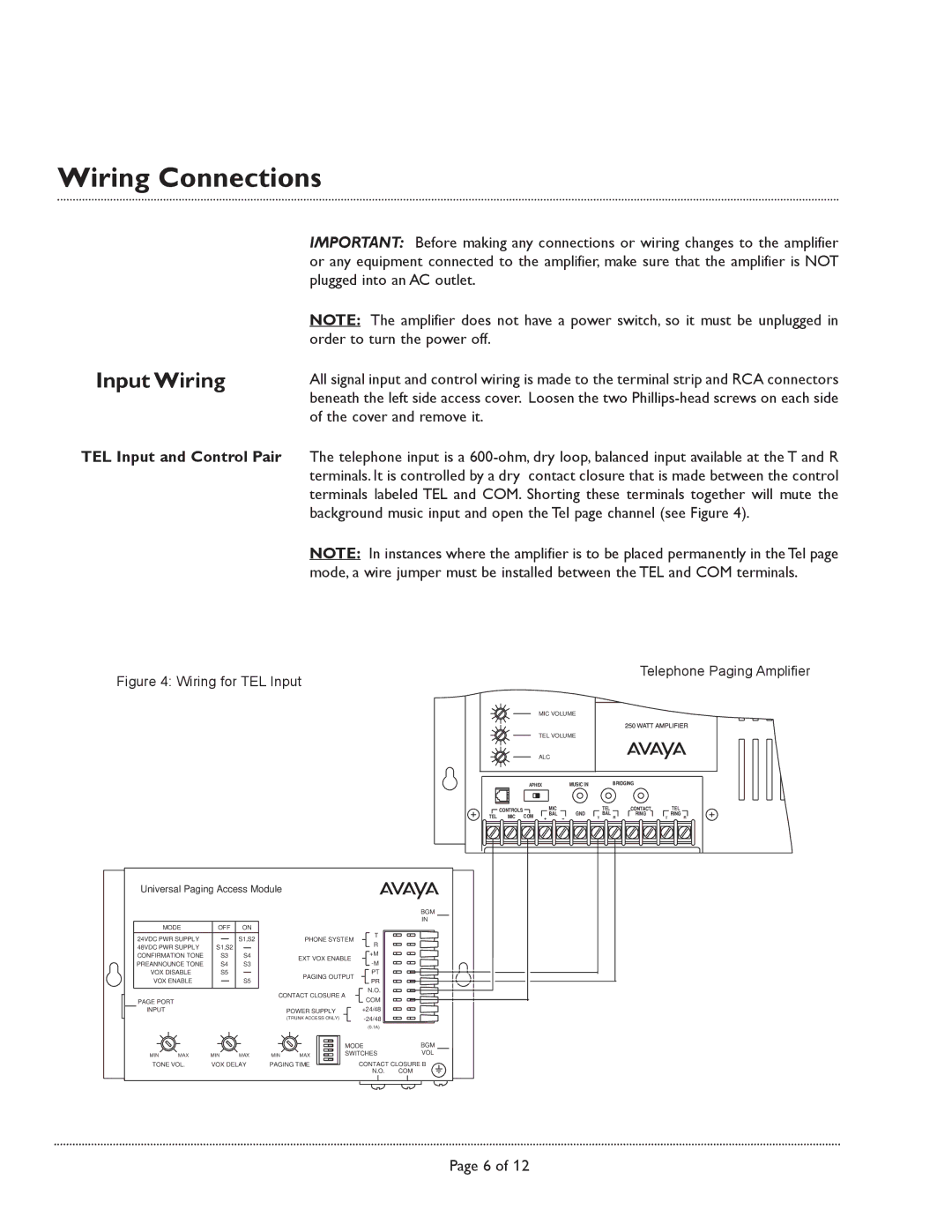
TEL Input and Control Pair The telephone input is a
NOTE: In instances where the amplifier is to be placed permanently in the Tel page mode, a wire jumper must be installed between the TEL and COM terminals.
Figure 4: Wiring for TEL Input
Telephone Paging Amplifier
MIC VOLUME
TEL VOLUME
ALC
APHEX | MUSIC IN | BRIDGING |
![]() CONTROLS
CONTROLS ![]()
TEL MIC COM
MIC |
| TEL |
BAL | GND | BAL |
+ | T | R |
CONTACT TEL
RING RING
T R
Universal Paging Access Module |
|
|
| ||||
|
|
|
|
|
|
| BGM |
|
|
|
|
|
|
| IN |
MODE | OFF | ON |
|
|
|
| |
24VDC PWR SUPPLY |
| S1,S2 |
|
| T |
| |
|
| PHONE SYSTEM |
| ||||
48VDC PWR SUPPLY | S1,S2 |
|
|
| R |
| |
|
|
| +M |
| |||
CONFIRMATION TONE | S3 | S4 |
|
|
| ||
| EXT VOX ENABLE |
| |||||
PREANNOUNCE TONE | S4 | S3 |
|
|
| ||
VOX DISABLE | S5 |
|
|
| PT |
| |
VOX ENABLE |
| S5 |
| PAGING OUTPUT |
| ||
|
|
| PR |
| |||
|
|
|
|
|
| N.O. |
|
|
|
|
| CONTACT CLOSURE A |
| ||
PAGE PORT |
|
|
|
|
| COM |
|
INPUT |
|
|
|
| POWER SUPPLY | +24/48 |
|
|
|
|
|
| (TRUNK ACCESS ONLY) |
| |
|
|
|
|
|
| (0.1A) |
|
|
|
|
|
|
| MODE | BGM |
MIN | MAX | MIN | MAX | MIN | MAX | SWITCHES | VOL |
TONE VOL. | VOX DELAY | PAGING TIME | CONTACT CLOSURE B | ||||
|
|
|
|
|
| N.O. | COM |
Page 6 of 12