AXIS 210/211 - Product Features 7
Overview
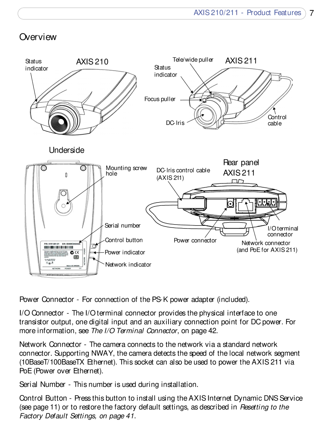
Status indicator
AXIS 210
Tele/wide puller AXIS 211
Status indicator
Focus puller
Control | |
cable |
Underside
Mounting screw | Rear panel | ||
AXIS 211 | |||
hole | |||
| (AXIS 211) |
|
Serial number |
| I/O terminal | |
|
| ||
Control button | Power connector | connector | |
Network connector | |||
|
| ||
Power indicator |
| (and PoE for AXIS 211) | |
|
| ||
Network indicator |
|
|
Power Connector - For connection of the
I/O Connector - The I/O terminal connector provides the physical interface to one transistor output, one digital input and an auxiliary connection point for DC power. For more information, see The I/O Terminal Connector, on page 42.
Network Connector - The camera connects to the network via a standard network connector. Supporting NWAY, the camera detects the speed of the local network segment (10BaseT/100BaseTX Ethernet). This socket can also be used to power the AXIS 211 via PoE (Power over Ethernet).
Serial Number - This number is used during installation.
Control Button - Press this button to install using the AXIS Internet Dynamic DNS Service (see page 11) or to restore the factory default settings, as described in Resetting to the Factory Default Settings, on page 41.