Page 4 | AXIS 243Q Blade Installation Guide |
 Hardware overview
AXIS 243Q Blade Video Server
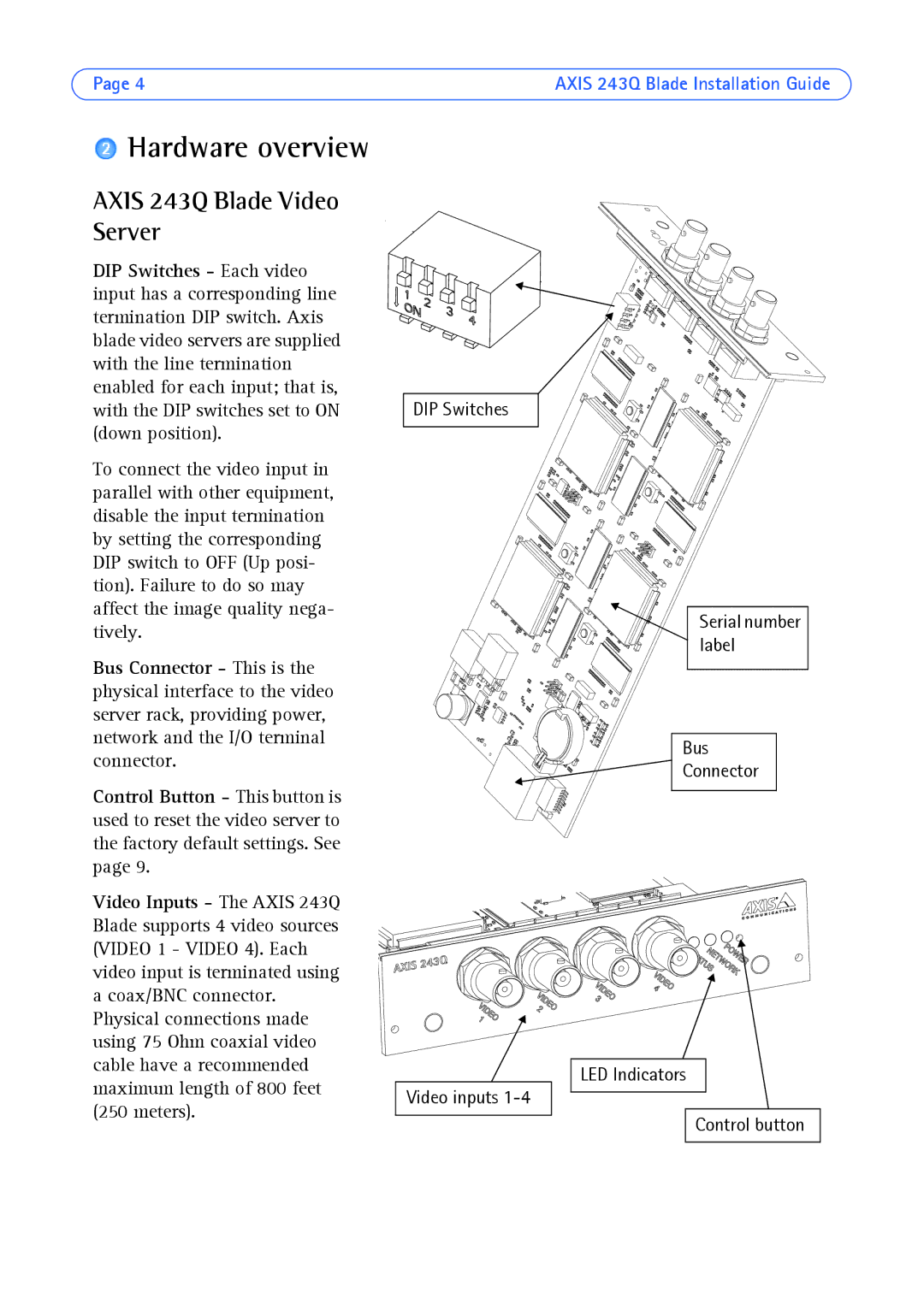
DIP Switches - Each video input has a corresponding line termination DIP switch. Axis blade video servers are supplied with the line termination enabled for each input; that is, with the DIP switches set to ON (down position).
To connect the video input in parallel with other equipment, disable the input termination by setting the corresponding DIP switch to OFF (Up posi- tion). Failure to do so may affect the image quality nega- tively.
Bus Connector - This is the physical interface to the video server rack, providing power, network and the I/O terminal connector.
Control Button - This button is used to reset the video server to the factory default settings. See page 9.
Video Inputs - The AXIS 243Q Blade supports 4 video sources (VIDEO 1 - VIDEO 4). Each video input is terminated using a coax/BNC connector. Physical connections made using 75 Ohm coaxial video cable have a recommended maximum length of 800 feet (250 meters).
DIP Switches
Video inputs
Serial number label
Bus
Connector
LED Indicators
Control button