|
| Table |
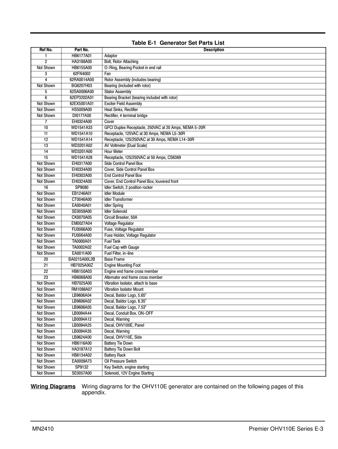
Ref No. | Part No. | Description |
|
|
|
1 | HB6177A01 | Adaptor |
2 | HA3188A00 | Bolt, Rotor Attaching |
Not Shown | HB6155A00 | |
3 | 62FN4002 | Fan |
4 | 62RA0014A00 | Rotor Assembly (includes bearing) |
Not Shown | BG6207H03 | Bearing (included with rotor) |
5 | 62SA0006A00 | Stator Assembly |
6 | 62EP3202A01 | Bearing Bracket (bearing included with rotor) |
Not Shown | 62EX5001A01 | Exciter Field Assembly |
Not Shown | HS5009A00 | Heat Sinks, Rectifier |
Not Shown | DI0177A00 | Rectifier, 4 terminal bridge |
7 | EH0324A00 | Cover |
10 | WD1541A33 | GFCI Duplex Receptacle, 250VAC at 20 Amps, NEMA |
11 | WD1541A10 | Receptacle, 125VAC at 30 Amps, NEMA |
12 | WD1541A14 | Receptacle, 125/250VAC at 30 Amps, NEMA |
13 | WD3201A02 | AV Voltmeter (Dual Scale) |
14 | WD3201A00 | Hour Meter |
15 | WD1541A28 | Receptacle, 125/250VAC at 50 Amps, CS6369 |
Not Shown | EH0317A00 | Side Control Panel Box |
Not Shown | EH0334A00 | Cover, Side Control Panel Box |
Not Shown | EH0302A00 | End Control Panel Box |
Not Shown | EH0324A00 | Cover, End Control Panel Box, louvered front |
16 | SP9080 | Idler Switch, 2 position rocker |
Not Shown | EB1246A01 | Idler Module |
Not Shown | CT0046A00 | Idler Transformer |
Not Shown | EA0040A01 | Idler Spring |
Not Shown | SE0059A00 | Idler Solenoid |
Not Shown | CK0070A05 | Circuit Breaker, 50A |
Not Shown | EM0027A04 | Voltage Regulator |
Not Shown | FU0066A00 | Fuse, Voltage Regulator |
Not Shown | FU0064A00 | Fuse Holder, Voltage Regulator |
Not Shown | TA0000A01 | Fuel Tank |
Not Shown | TA0002A02 | Fuel Cap with Gauge |
Not Shown | EA0011A00 | Fuel Filter, |
20 | BA0215A00L2B | Base Frame |
21 | HB7025A00Z | Engine Mounting Foot |
22 | HB6150A03 | Engine end frame cross member |
23 | HB6068A00 | Alternator end frame cross member |
Not Shown | HB7025A00 | Vibration Isolator, attach to base |
Not Shown | RM1088A07 | Vibration Isolator Mount |
Not Shown | LB9606A04 | Decal, Baldor Logo, 5.65" |
Not Shown | LB9606A02 | Decal, Baldor Logo, 6.35" |
Not Shown | LB9606A05 | Decal, Baldor Logo, 7.53" |
Not Shown | LB0094A44 | Decal, Conduit Box, |
Not Shown | LB0094A12 | Decal, Warning |
Not Shown | LB0094A25 | Decal, OHV100E, Panel |
Not Shown | LB0094A35 | Decal, Warning |
Not Shown | LB9624A00 | Decal, OHV110E, Side |
Not Shown | HB6116A00 | Battery Tie Down |
Not Shown | HA3187A12 | Battery Tie Down Bolt |
Not Shown | HB6134A02 | Battery Rack |
Not Shown | EA0009A73 | Oil Pressure Switch |
Not Shown | SP9132 | Key Switch, engine starting |
Not Shown | SE0057A00 | Solenoid, 12V Engine Starting |
Wiring Diagrams Wiring diagrams for the OHV110E generator are contained on the following pages of this appendix.
MN2410 | Premier OHV110E Series |