| Table | |
|
|
|
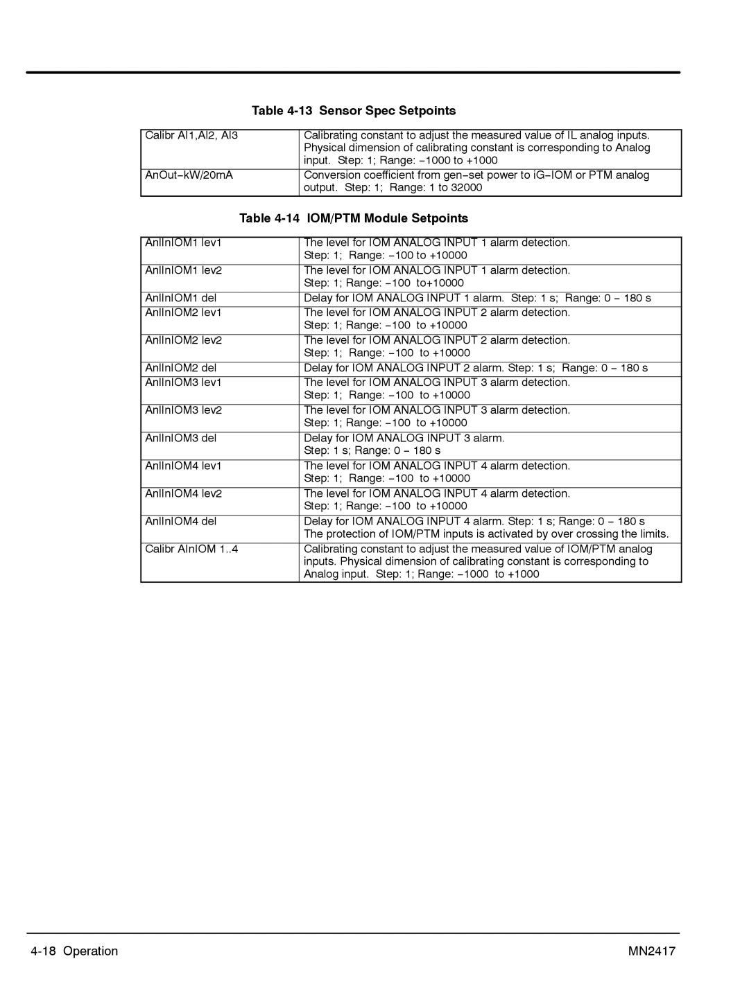
Calibr AI1,AI2, AI3 |
| Calibrating constant to adjust the measured value of IL analog inputs. |
|
| Physical dimension of calibrating constant is corresponding to Analog |
|
| input. Step: 1; Range: −1000 to +1000 |
|
|
|
AnOut−kW/20mA |
| Conversion coefficient from gen−set power to iG−IOM or PTM analog |
|
| output. Step: 1; Range: 1 to 32000 |
| Table | |
|
|
|
AnlInIOM1 lev1 |
| The level for IOM ANALOG INPUT 1 alarm detection. |
|
| Step: 1; Range: −100 to +10000 |
|
|
|
AnlInIOM1 lev2 |
| The level for IOM ANALOG INPUT 1 alarm detection. |
|
| Step: 1; Range: −100 to+10000 |
|
|
|
AnlInIOM1 del |
| Delay for IOM ANALOG INPUT 1 alarm. Step: 1 s; Range: 0 − 180 s |
AnlInIOM2 lev1 |
| The level for IOM ANALOG INPUT 2 alarm detection. |
|
| Step: 1; Range: −100 to +10000 |
|
|
|
AnlInIOM2 lev2 |
| The level for IOM ANALOG INPUT 2 alarm detection. |
|
| Step: 1; Range: −100 to +10000 |
|
|
|
AnlInIOM2 del |
| Delay for IOM ANALOG INPUT 2 alarm. Step: 1 s; Range: 0 − 180 s |
AnlInIOM3 lev1 |
| The level for IOM ANALOG INPUT 3 alarm detection. |
|
| Step: 1; Range: −100 to +10000 |
|
|
|
AnlInIOM3 lev2 |
| The level for IOM ANALOG INPUT 3 alarm detection. |
|
| Step: 1; Range: −100 to +10000 |
|
|
|
AnlInIOM3 del |
| Delay for IOM ANALOG INPUT 3 alarm. |
|
| Step: 1 s; Range: 0 − 180 s |
|
|
|
AnlInIOM4 lev1 |
| The level for IOM ANALOG INPUT 4 alarm detection. |
|
| Step: 1; Range: −100 to +10000 |
|
|
|
AnlInIOM4 lev2 |
| The level for IOM ANALOG INPUT 4 alarm detection. |
|
| Step: 1; Range: −100 to +10000 |
|
|
|
AnlInIOM4 del |
| Delay for IOM ANALOG INPUT 4 alarm. Step: 1 s; Range: 0 − 180 s |
|
| The protection of IOM/PTM inputs is activated by over crossing the limits. |
|
|
|
Calibr AInIOM 1..4 |
| Calibrating constant to adjust the measured value of IOM/PTM analog |
|
| inputs. Physical dimension of calibrating constant is corresponding to |
|
| Analog input. Step: 1; Range: −1000 to +1000 |
MN2417 |
