båÅçêÉ=smñ=fåëí~ää~íáçå=dìáÇÉ
VPx Hardware
smñ=e~êÇï~êÉ
The following topics are discussed in this section:
•
•
•
•
•
•
VPx Front Panel
VPx Rear Panel
VPx M/E Connectors
M/E Connector Priority
M/E Input Notes
Program Output Notes
smñ=cêçåí=m~åÉä
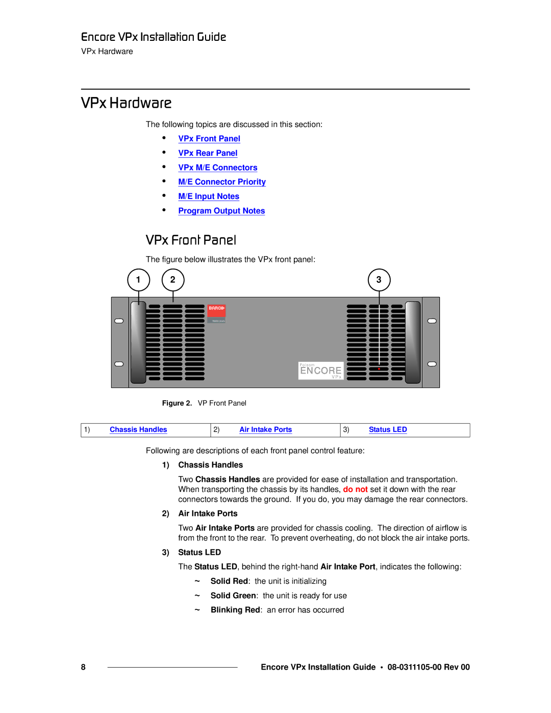
The figure below illustrates the VPx front panel:
1 | 2 | 3 |
|
| Visibly yours |
|
| Folsom |
|
| ENCORE |
|
| V P x |
Figure 2. VP Front Panel
1)Chassis Handles
2)Air Intake Ports
3)Status LED
Following are descriptions of each front panel control feature:
1)Chassis Handles
Two Chassis Handles are provided for ease of installation and transportation. When transporting the chassis by its handles, do not set it down with the rear connectors towards the ground. If you do, you may damage the rear connectors.
2)Air Intake Ports
Two Air Intake Ports are provided for chassis cooling. The direction of airflow is from the front to the rear. To prevent overheating, do not block the air intake ports.
3)Status LED
The Status LED, behind the
~
~
~
Solid Red: the unit is initializing
Solid Green: the unit is ready for use
Blinking Red: an error has occurred
8 |
| Encore VPx Installation Guide • |
|
