Setting Menu
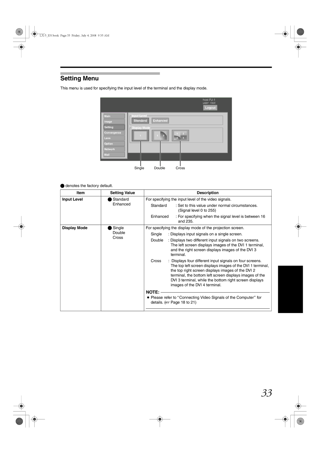
This menu is used for specifying the input level of the terminal and the display mode.
Main
Image
Setting
Convergence
Lens
Option
Network
host
Logout
Input Level
Standard ![]()
![]() Enhanced
Enhanced
Display Mode
1 2
1 | 1 | 3 |
3 4
Single Double Cross
denotes the factory default.
Item | Setting Value |
|
| Description |
Input Level | Standard | For specifying the input level of the video signals. | ||
| Enhanced | Standard |
| : Set to this value under normal circumstances. |
|
|
| ||
|
|
|
| (Signal level 0 to 255) |
|
| Enhanced | : For specifying when the signal level is between 16 | |
|
|
|
| and 235. |
|
|
| ||
Display Mode | Single | For specifying the display mode of the projection screen. | ||
| Double | Single | : Displays input signals on a single screen. | |
| Cross | |||
| Double | : Displays two different input signals on two screens. | ||
|
| |||
|
|
|
| The left screen displays images of the DVI 1 terminal, |
|
|
|
| and the right screen displays images of the DVI 3 |
|
|
|
| terminal. |
|
| Cross | : Displays four different input signals on four screens. | |
|
|
|
| The top left screen displays images of the DVI 1 terminal, |
|
|
|
| the top right screen displays images of the DVI 2 |
|
|
|
| terminal, the bottom left screen displays images of the |
|
|
|
| DVI 3 terminal, while the bottom right screen displays |
|
|
|
| images of the DVI 4 terminal. |
NOTE:
●Please refer to AConnecting Video Signals of the ComputerB for details. (A Page 18 to 21)
33