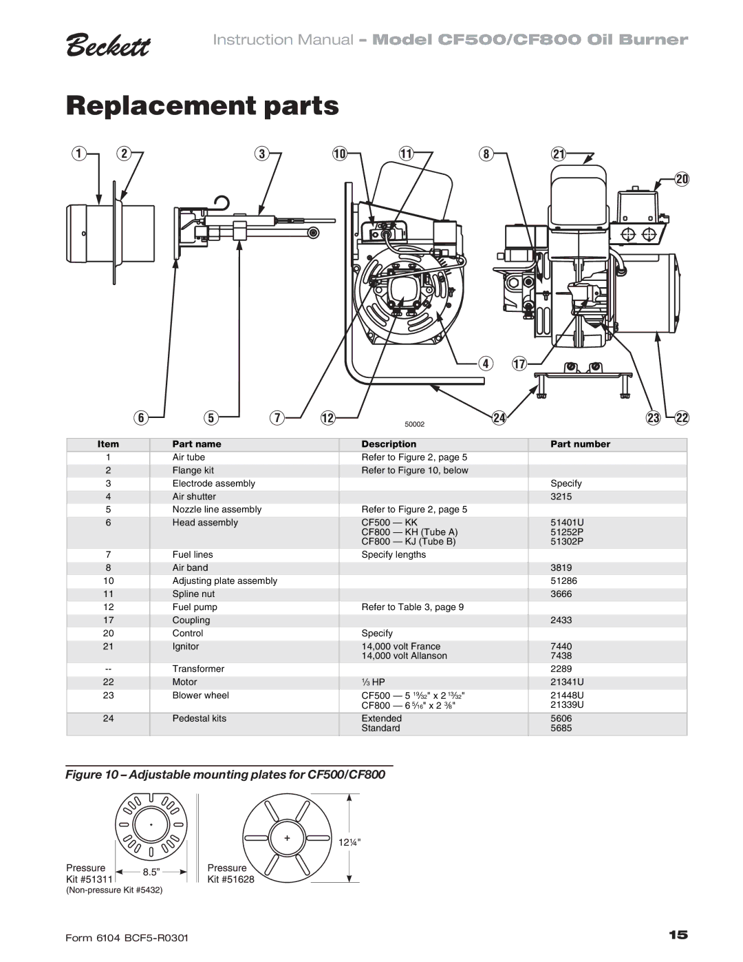
CF 500/800 specifications
The Beckett CF 500/800 is a high-performance oil burner designed for residential and commercial heating applications. This advanced model incorporates cutting-edge technologies and innovative features that enhance energy efficiency, reliability, and ease of use. Engineered for optimal combustion, the CF 500/800 delivers consistent heating with lower emissions, making it an environmentally friendly choice.One of the standout characteristics of the Beckett CF 500/800 is its unique combustion chamber design. This feature ensures complete fuel combustion, maximizing the energy extracted from the oil while minimizing the release of pollutants. The advanced burner head not only improves efficiency but also reduces noise levels during operation, providing a quieter heating experience.
The CF 500/800 is equipped with an electronic ignition system, which enhances startup reliability. This technology eliminates the need for a constant pilot flame, contributing to energy savings and improved safety. Additionally, the model includes an integrated flame sensor that monitors the combustion process, ensuring that the burner operates optimally.
User-friendly controls make the Beckett CF 500/800 easy to operate and maintain. The burner is designed with accessibility in mind, allowing technicians to service and adjust components without extensive disassembly. Its modular construction further simplifies maintenance, enabling quick repairs and minimizing downtime.
In terms of compatibility, the CF 500/800 can be integrated with various heating systems, including forced hot air, hot water, and steam systems. This versatility makes it suitable for a wide range of applications, from residential homes to larger commercial buildings.
Safety features are paramount in the design of the Beckett CF 500/800. It incorporates a dual technology safety shut-off mechanism, protecting against potential hazards and ensuring peace of mind for users.
In summary, the Beckett CF 500/800 stands out in the competitive oil burner market due to its efficient combustion technology, user-friendly design, and robust safety features. Its ability to provide consistent and reliable heating while prioritizing environmental concerns confirms its position as a leading choice for those seeking a dependable oil burner solution. With the CF 500/800, Beckett continues to deliver quality and innovation in heating technology.

