XENYX 1622FX/1832FX/2222FX/2442FX
sufficiently high level. Take care to ensure that the clip LED only lights up at peak levels. If it is lit constantly, you are overloading the effects processor and this could cause unpleasant distortion.
PROGRAM
You can select the effect preset by turning the PROGRAM control. The display flashes with the number of the current preset. To recall the selected preset, press on the button; the flashing stops. You can also recall the selected preset with the foot switch.
5. REAR PANEL CONNECTORS
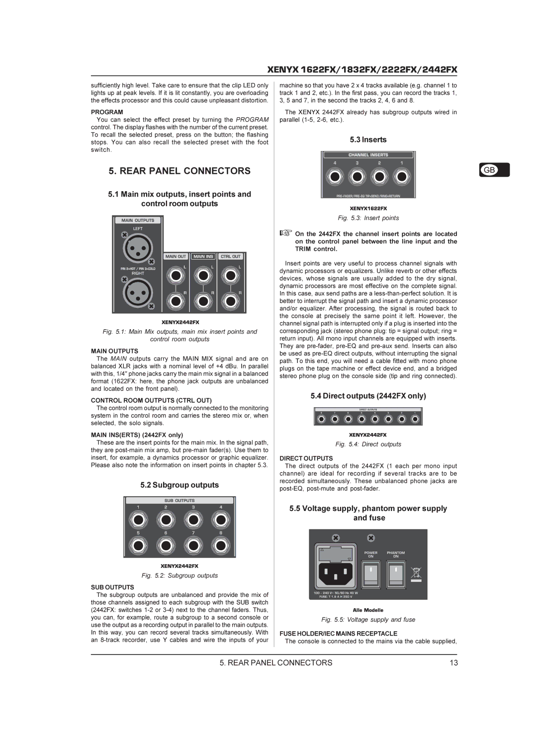
5.1Main mix outputs, insert points and control room outputs
Fig. 5.1: Main Mix outputs, main mix insert points and
control room outputs
MAIN OUTPUTS
The MAIN outputs carry the MAIN MIX signal and are on balanced XLR jacks with a nominal level of +4 dBu. In parallel with this, 1/4" phone jacks carry the main mix signal in a balanced format (1622FX: here, the phone jack outputs are unbalanced and located on the front panel).
CONTROL ROOM OUTPUTS (CTRL OUT)
The control room output is normally connected to the monitoring system in the control room and carries the stereo mix or, when selected, the solo signals.
MAIN INS(ERTS) (2442FX only)
These are the insert points for the main mix. In the signal path, they are
5.2 Subgroup outputs
Fig. 5.2: Subgroup outputs
SUB OUTPUTS
The subgroup outputs are unbalanced and provide the mix of those channels assigned to each subgroup with the SUB switch (2442FX: switches
machine so that you have 2 x 4 tracks available (e.g. channel 1 to track 1 and 2, etc.). In the first pass, you can record the tracks 1, 3, 5 and 7, in the second the tracks 2, 4, 6 and 8.
The XENYX 2442FX already has subgroup outputs wired in parallel
5.3 Inserts
Fig. 5.3: Insert points
+On the 2442FX the channel insert points are located on the control panel between the line input and the TRIM control.
Insert points are very useful to process channel signals with dynamic processors or equalizers. Unlike reverb or other effects devices, whose signals are usually added to the dry signal, dynamic processors are most effective on the complete signal. In this case, aux send paths are a
5.4 Direct outputs (2442FX only)
Fig. 5.4: Direct outputs
DIRECT OUTPUTS
The direct outputs of the 2442FX (1 each per mono input channel) are ideal for recording if several tracks are to be recorded simultaneously. These unbalanced phone jacks are
5.5Voltage supply, phantom power supply and fuse
Fig. 5.5: Voltage supply and fuse
FUSE HOLDER/IEC MAINS RECEPTACLE
The console is connected to the mains via the cable supplied,
5. REAR PANEL CONNECTORS | 13 |