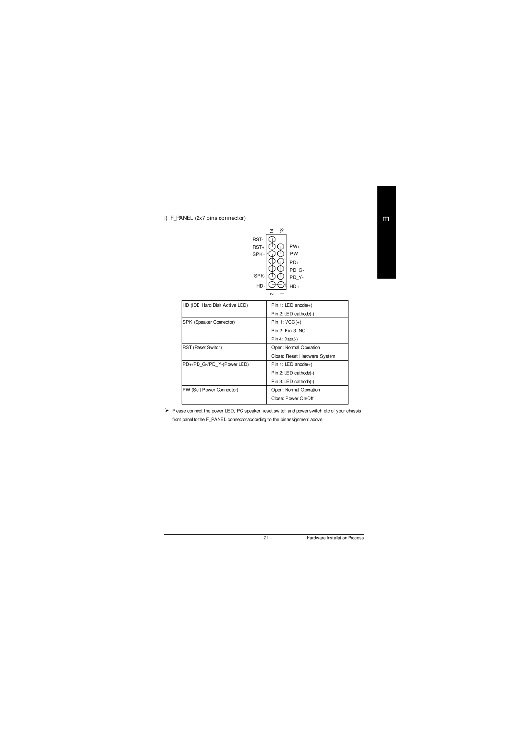
I) F_PANEL (2x7 pins connector)
14 | 13 |
| |||
RST- |
|
|
|
| PW+ |
|
|
|
| ||
RST+ |
|
|
|
| |
|
|
|
| ||
SPK+ | 1 |
|
|
| PW- |
|
| ||||
|
|
|
|
| PD+ |
|
|
|
| ||
SPK- |
|
|
|
| PD_G- |
|
|
| 1 | PD_Y- | |
|
| ||||
HD - |
|
|
| HD+ | |
|
| ||||
2 | 1 |
| |||
|
|
| |||
HD (IDE Hard Disk Active LED) |
| Pin 1: LED anode(+) | |||
|
| Pin 2: LED | |||
|
|
| |||
SPK (Speaker Connector) |
| Pin 1: VCC(+) | |||
|
| Pin 2- P in 3: NC | |||
|
| Pin 4: | |||
|
|
| |||
RST (Reset Switch) |
| Open: Normal Operation | |||
|
| Close: Reset Hardware System | |||
|
|
| |||
| Pin 1: LED anode(+) | ||||
|
| Pin 2: LED | |||
|
| Pin 3: LED | |||
|
|
| |||
PW (Soft Power Connector) |
| Open: Normal Operation | |||
|
| Close: Power On/Off | |||
|
|
|
|
|
|
ØPlease connect the power LED, PC speaker, reset switch and power switch etc of your chassis front panel to the F_PANEL connectoraccording to the pin assignment above.
E
n
- 21 - | Hardware Installation Process |