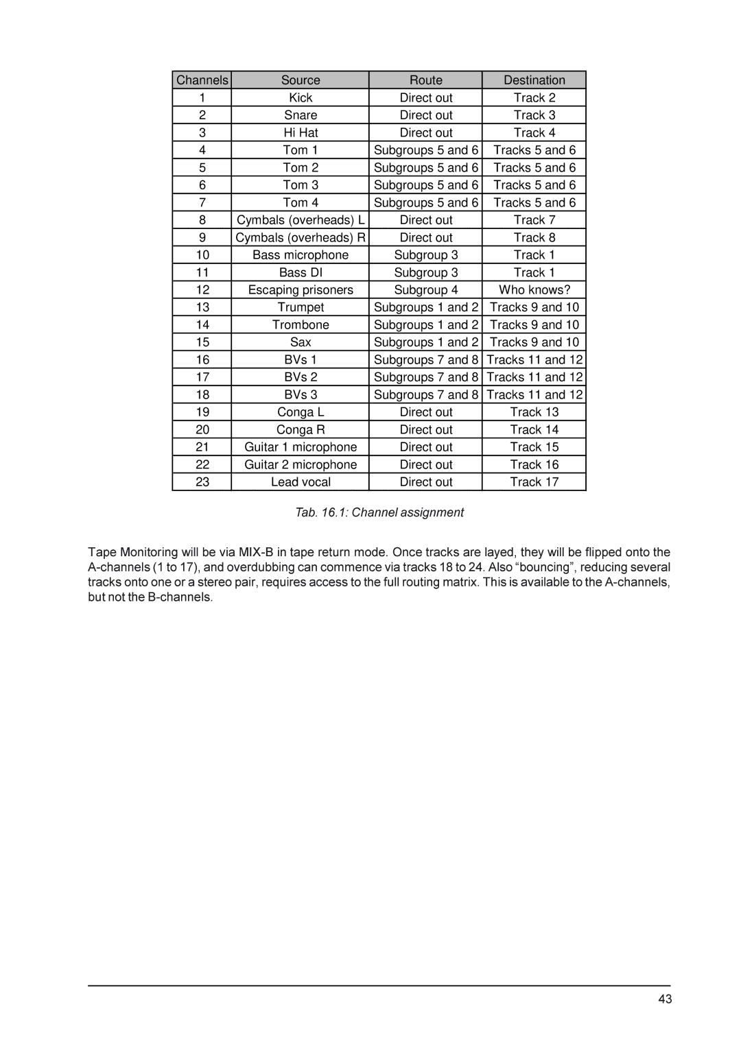
Channels | Source | Route | Destination |
|
1 | Kick | Direct out | Track 2 |
|
2 | Snare | Direct out | Track 3 |
|
3 | Hi Hat | Direct out | Track 4 |
|
4 | Tom 1 | Subgroups 5 and 6 | Tracks 5 and | 6 |
5 | Tom 2 | Subgroups 5 and 6 | Tracks 5 and | 6 |
6 | Tom 3 | Subgroups 5 and 6 | Tracks 5 and | 6 |
7 | Tom 4 | Subgroups 5 and 6 | Tracks 5 and | 6 |
8 | Cymbals (overheads) L | Direct out | Track 7 |
|
9 | Cymbals (overheads) R | Direct out | Track 8 |
|
10 | Bass microphone | Subgroup 3 | Track 1 |
|
11 | Bass DI | Subgroup 3 | Track 1 |
|
12 | Escaping prisoners | Subgroup 4 | Who knows? | |
13 | Trumpet | Subgroups 1 and 2 | Tracks 9 and 10 | |
14 | Trombone | Subgroups 1 and 2 | Tracks 9 and 10 | |
15 | Sax | Subgroups 1 and 2 | Tracks 9 and 10 | |
16 | BVs 1 | Subgroups 7 and 8 | Tracks 11 and | 12 |
17 | BVs 2 | Subgroups 7 and 8 | Tracks 11 and | 12 |
18 | BVs 3 | Subgroups 7 and 8 | Tracks 11 and | 12 |
19 | Conga L | Direct out | Track 13 |
|
20 | Conga R | Direct out | Track 14 |
|
21 | Guitar 1 microphone | Direct out | Track 15 |
|
22 | Guitar 2 microphone | Direct out | Track 16 |
|
23 | Lead vocal | Direct out | Track 17 |
|
Tab. 16.1: Channel assignment
Tape Monitoring will be via
43