INSTALLATION
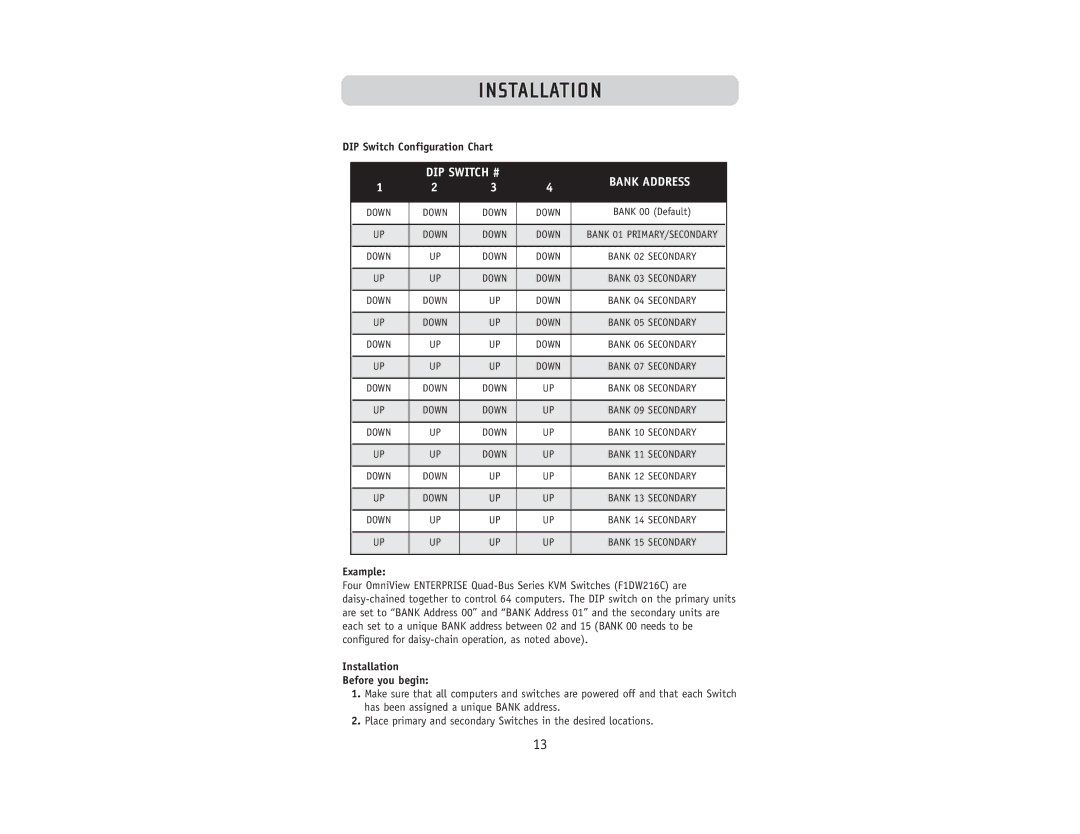
DIP Switch Configuration Chart
| DIP SWITCH # |
| BANK ADDRESS | ||
1 | 2 | 3 | 4 | ||
| |||||
|
|
|
|
| |
DOWN | DOWN | DOWN | DOWN | BANK 00 (Default) | |
|
|
|
|
| |
UP | DOWN | DOWN | DOWN | BANK 01 PRIMARY/SECONDARY | |
|
|
|
|
| |
DOWN | UP | DOWN | DOWN | BANK 02 SECONDARY | |
|
|
|
|
| |
UP | UP | DOWN | DOWN | BANK 03 SECONDARY | |
|
|
|
|
| |
DOWN | DOWN | UP | DOWN | BANK 04 SECONDARY | |
|
|
|
|
| |
UP | DOWN | UP | DOWN | BANK 05 SECONDARY | |
|
|
|
|
| |
DOWN | UP | UP | DOWN | BANK 06 SECONDARY | |
|
|
|
|
| |
UP | UP | UP | DOWN | BANK 07 SECONDARY | |
|
|
|
|
| |
DOWN | DOWN | DOWN | UP | BANK 08 SECONDARY | |
|
|
|
|
| |
UP | DOWN | DOWN | UP | BANK 09 SECONDARY | |
|
|
|
|
| |
DOWN | UP | DOWN | UP | BANK 10 SECONDARY | |
|
|
|
|
| |
UP | UP | DOWN | UP | BANK 11 SECONDARY | |
|
|
|
|
| |
DOWN | DOWN | UP | UP | BANK 12 SECONDARY | |
|
|
|
|
| |
UP | DOWN | UP | UP | BANK 13 SECONDARY | |
|
|
|
|
| |
DOWN | UP | UP | UP | BANK 14 SECONDARY | |
|
|
|
|
| |
UP | UP | UP | UP | BANK 15 SECONDARY | |
|
|
|
|
| |
Example:
Four OmniView ENTERPRISE
Installation
Before you begin:
1.Make sure that all computers and switches are powered off and that each Switch has been assigned a unique BANK address.
2.Place primary and secondary Switches in the desired locations.
13
