and COMPLETE RELEASES (the number of applications depends on how much the slack was
BRAKE MAINTENANCE INSPECTION
Note: Make certain the vehicle has been prepared according to the instructions under the heading GENERAL SAFETY GUIDELINES.
The following test can be used to inspect the maintenance condition of the foundation brake and to determine how much of the chamber stroke is caused by the condition of the foundation brake.
1.Always chock the wheels to keep vehicle from moving.
2.Raise the axle so the wheel can be rotated.
3.Adjust the slack adjuster to produce light brake drag with wheel rotation.
4.Apply the brake to
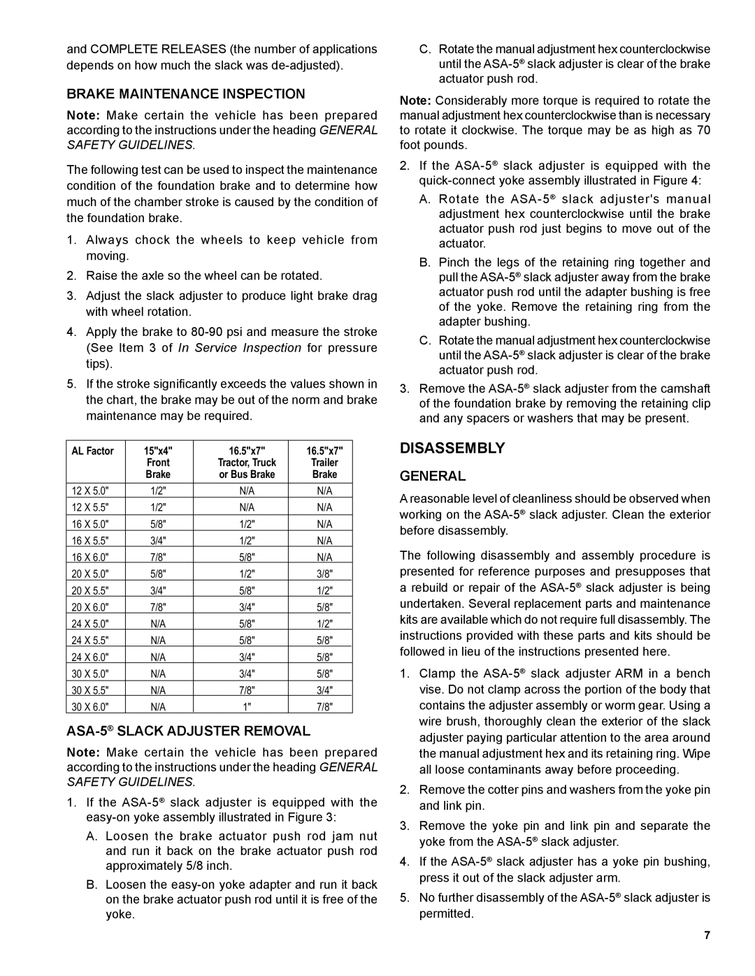
5.If the stroke signifi cantly exceeds the values shown in the chart, the brake may be out of the norm and brake maintenance may be required.
AL Factor | 15"x4" | 16.5"x7" | 16.5"x7" |
| |
|
|
|
|
|
|
| Front | Tractor, Truck | Trailer |
| |
| Brake | or Bus Brake | Brake |
| |
12 X 5.0" | 1/2" | N/A | N/A |
| |
|
|
|
|
|
|
12 X 5.5" | 1/2" | N/A | N/A |
| |
|
|
|
|
|
|
16 X 5.0" | 5/8" | 1/2" | N/A |
| |
16 X 5.5" | 3/4" | 1/2" | N/A |
| |
|
|
|
|
|
|
16 X 6.0" | 7/8" | 5/8" | N/A |
| |
20 X 5.0" | 5/8" | 1/2" | 3/8" |
|
|
|
|
|
|
|
|
20 X 5.5" | 3/4" | 5/8" | 1/2" |
|
|
20 X 6.0" | 7/8" | 3/4" | 5/8" |
|
|
|
|
|
|
|
|
24 X 5.0" | N/A | 5/8" | 1/2" |
|
|
24 X 5.5" | N/A | 5/8" | 5/8" |
|
|
|
|
|
|
|
|
24 X 6.0" | N/A | 3/4" | 5/8" |
|
|
30 X 5.0" | N/A | 3/4" | 5/8" |
|
|
|
|
|
|
|
|
30 X 5.5" | N/A | 7/8" | 3/4" |
|
|
30 X 6.0" | N/A | 1" | 7/8" |
|
|
|
|
|
|
|
|
ASA-5® SLACK ADJUSTER REMOVAL
Note: Make certain the vehicle has been prepared according to the instructions under the heading GENERAL SAFETY GUIDELINES.
1.If the
A.Loosen the brake actuator push rod jam nut and run it back on the brake actuator push rod approximately 5/8 inch.
B.Loosen the
C.Rotate the manual adjustment hex counterclockwise until the
Note: Considerably more torque is required to rotate the manual adjustment hex counterclockwise than is necessary to rotate it clockwise. The torque may be as high as 70 foot pounds.
2.If the
A.Rotate the
B.Pinch the legs of the retaining ring together and pull the
C.Rotate the manual adjustment hex counterclockwise until the
3.Remove the
DISASSEMBLY
GENERAL
A reasonable level of cleanliness should be observed when working on the
The following disassembly and assembly procedure is presented for reference purposes and presupposes that a rebuild or repair of the
1.Clamp the
2.Remove the cotter pins and washers from the yoke pin and link pin.
3.Remove the yoke pin and link pin and separate the yoke from the
4.If the
5.No further disassembly of the
7