with the end of the brake actuator push rod. Install the retaining ring on the adapter bushing, making certain it is in the adapter bushing groove. Turn the
5.Run the brake actuator push rod jam nut down against the adapter or adapter bushing. Hold the adapter or adapter bushing hex with a wrench and tighten the jam nut to
6.Manually adjust the brakes.
Note: The vehicle brakes should be adjusted using the vehicle or brake manufacturer’s recommendation. If they are not available, the following procedure can be used: Rotate the manual adjustment hex clockwise until the linings are snug against the drum. Turn the adjustment hex counterclockwise 1/2 turn. Pull the actuator push rod to confi rm that approximately 1/2 inch of push rod free stroke exists. Apply 85 psi and check that the push rod stroke is below the readjustment limit. If the stroke exceeds the readjustment limit, check the condition of the foundation brake. Refer to Brake Maintenance Inspection.
7.Manually uncage the spring brakes before returning the vehicle to service.
8.With the
PREVENTIVE MAINTENANCE
Important: Always review the Bendix Warranty Policy before performing any intrusive maintenance procedures. A warranty may be voided if intrusive maintenance is performed during the warranty period.
No two vehicles operate under identical conditions, as a result, maintenance intervals may vary. Experience is a valuable guide in determining the best maintenance interval for air brake system components.At a minimum, the
Visually check for physical damage such as broken air lines and broken or missing parts.
Every 25,000 miles, or 3 months, or 500 operating hours or at the time of routine vehicle chassis lubrication, whichever occurs first, the following steps should be followed (Also observe any shorter brake adjustment inspections or maintenance intervals specifi ed by the vehicle manufacturer):
1.Lubricate the automatic slack adjuster through the lube fi tting with a quality multipurpose chassis lubricant (N.L.G.I. Grade 2).
Lubricate the slack adjuster until clean lubricant fl ows from the grease relief opening in the boot.
2.Perform the In Service Inspection described in this manual.
IN SERVICE INSPECTION
1.Apply and release the vehicle brakes several times while observing the
2.Inspect the
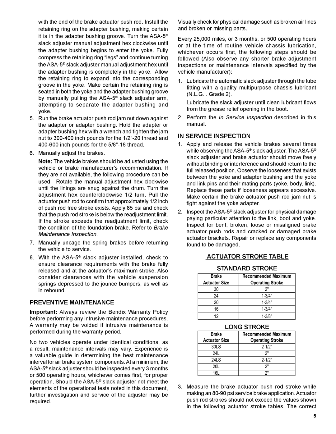
ACTUATOR STROKE TABLE
STANDARD STROKE
| Brake | Recommended Maximum |
|
|
|
|
|
| Actuator Size | Operating Stroke |
|
| 30 | 2" |
|
|
|
|
|
| 24 |
| |
|
|
|
|
| 20 |
| |
|
|
|
|
| 16 |
| |
|
|
|
|
| 12 |
| |
|
|
|
|
LONG STROKE
| Brake | Recommended Maximum |
|
| Actuator Size | Operating Stroke |
|
| 30LS |
| |
|
|
|
|
| 24L | 2" |
|
|
|
|
|
| 24LS |
| |
|
|
|
|
| 20L | 2" |
|
| 16L | 2" |
|
3.Measure the brake actuator push rod stroke while making an
5