Tank (Nipple) Mounted
The BR9235™ MRV can be
Bracket (Chassis) Mounted
The BR9235™ MRV provides an option with a bracket for frame mounting directly to the trailer frame rail or crossmember. It is recommended to use two Grade 5, 3/8‑16 bolts, torqued to 180 – 220
J1708/J1587 DIAGNOSTIC LINK
The Premium
Ignition power must be provided to the
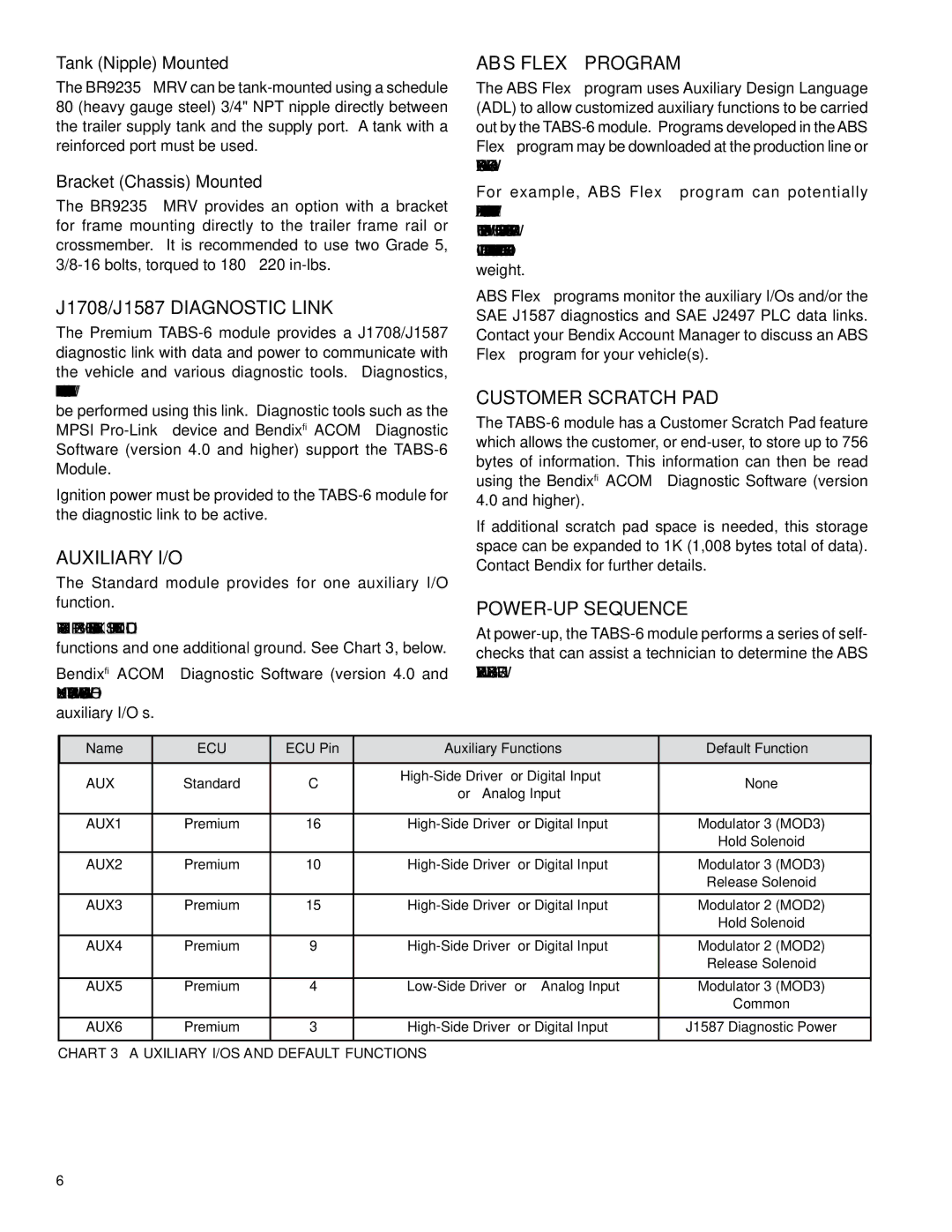
AUXILIARY I/O
The Standard module provides for one auxiliary I/O function.
The Premium module provides for up to five auxiliary functions and one additional ground. See Chart 3, below.
Bendix® ACOM™ Diagnostic Software (version 4.0 and higher) supports the configuration of the
auxiliary I/O’s.
ABs Flex™ Program
The ABS Flex™ program uses Auxiliary Design Language (ADL) to allow customized auxiliary functions to be carried out by the
For example, ABS Flex™ program can potentially communicate the status of: tire inflation and/or temperature; reefer temperature; load presence; slider pin position; lift axle position; proximity/reverse alarm; and vehicle weight.
ABS Flex™ programs monitor the auxiliary I/Os and/or the SAE J1587 diagnostics and SAE J2497 PLC data links. Contact your Bendix Account Manager to discuss an ABS Flex™ program for your vehicle(s).
CUSTOMER SCRATCH PAD
The
If additional scratch pad space is needed, this storage space can be expanded to 1K (1,008 bytes total of data). Contact Bendix for further details.
POWER-UP SEQUENCE
At
Name | ECU | ECU Pin | Auxiliary Functions | Default Function | |
AUX | Standard | C | • | None | |
or • Analog Input | |||||
|
|
|
| ||
|
|
|
|
| |
AUX1 | Premium | 16 | • | Modulator 3 (MOD3) | |
|
|
|
| Hold Solenoid | |
AUX2 | Premium | 10 | • | Modulator 3 (MOD3) | |
|
|
|
| Release Solenoid | |
|
|
|
|
| |
AUX3 | Premium | 15 | • | Modulator 2 (MOD2) | |
|
|
|
| Hold Solenoid | |
|
|
|
|
| |
AUX4 | Premium | 9 | • | Modulator 2 (MOD2) | |
|
|
|
| Release Solenoid | |
|
|
|
|
| |
AUX5 | Premium | 4 | • | Modulator 3 (MOD3) | |
|
|
|
| Common | |
|
|
|
|
| |
AUX6 | Premium | 3 | • | J1587 Diagnostic Power | |
|
|
|
|
|
CHART 3 – Auxiliary I/Os and Default Functions