Power/ABS Indicator Lamp Connector
The TABS-6 module pigtail uses a TTMA RP 97-99 5-pin Packard Weather Pack connector for brake light power, constant power, ground and the trailer-mounted ABS indicator lamp.
The Power/ABS indicator lamp lead of the pigtail harness is available in several lengths to satisfy most installation requirements (e.g. slider axles).
Wheel Speed Sensor Connectors
Two 2-pin connectors are provided for additional wheel speed sensors for 4S ABS applications. These 2-pin connectors are labeled Additional Sensor Left (SAL), and Additional Sensor Right (SAR). Extension cables are available in various lengths from Bendix.
ABS Modulator Connectors
On Premium TABS-6 module pigtail harnesses, one or two modulator connectors are provided for trailers using two or three modulators. These 3-pin connectors are labeled MOD2 and MOD3. (Note: MOD1 designates the internal modulator of the TABS-6 module). Remote modulator harnesses are available in many lengths to satisfy most installation requirements.
Diagnostic Connector
Premium TABS-6 module pigtail harnesses provide a 4- pin diagnostic connection for a diagnostic tool to monitor ECU ignition power, ground and data information. Remote diagnostic cables are available from Bendix to provide a standard J1708/J1587 diagnostic port at the side of the trailer.
Auxiliary I/O Connector
Standard TABS-6 module pigtails provide an option for a single auxiliary I/O. An optional auxiliary connector provides a connection to the TABS-6 module auxiliary I/O ECU pins. Premium ECU pigtails provides an option for up to six auxiliary I/O’s.
POWER AND GROUND
Trailer electrical power is supplied to the TABS-6 module from the ignition and brake light circuits. See Charts 1 and 2 for output values and pin locations.
Function Mode | Value |
Operating Range | 8.0 to 16.0 VDC |
| |
ECU Active | 135 mA @ 12 VDC |
| |
ABS Active | 3.7 A @ 12 VDC |
(1 Modulator) | |
| |
ABS Active | 5.2 A @ 12 VDC |
(2 Modulators) | |
| |
CHART 1 – Values for Outputs
| | 7-Pin | 5-Pin | 5-Pin | 18-Pin |
| Circuit | Trailer | ABS | ECU | ECU |
| | Conn. | Conn. | Conn. | Conn. |
| Ignition Power | 7 | B | B | 6 |
| PLC (Blue Wire) |
| | | | |
| | | | | |
| Brake Light | | | | |
| Power | 4 | A | A | 12 |
| (Red Wire) | | | | |
| | | | | |
| Ground | 1 | E | E | 18 |
| (White Wire) |
| | | | |
| | | | | |
| Indicator Lamp | N/A | D | D | 5 |
| (White/green |
| Wire) | | | | |
| | | | | |
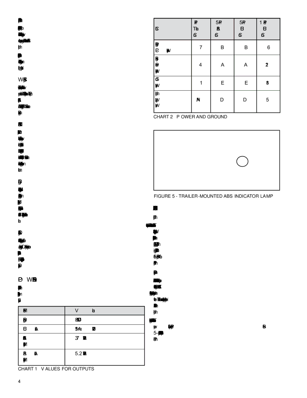
CHART 2 – Power and Ground
FIGURE 5 - trailer-mounted ABS indicator lamp
ABS INDICATOR LAMP
Trailer-mounted Lamp
The TABS-6 module controls an ABS indicator lamp to show the trailer ABS status. With power supplied by the towing vehicle, the module illuminates the ABS indicator lamp by providing a 12.0 VDC signal. (The other side of the lamp is grounded.) The ABS indicator lamp output uses Pin D of the 5-pin Standard module connector, and Pin 5 of the 18-pin Premium module connector.
Dash-mounted Lamp (PLC Controlled)
TABS-6 modules use SAE J2497 standards to support Power Line Carrier (PLC) communication. The TABS-6 module transmits a signal over the power line to the towing vehicle. This information is used by towing vehicle’s ABS controller to know when to illuminate the trailer ABS indicator lamp mounted on the dash.
The status of the trailer ABS is transmitted over the ignition power wire (blue wire of the J560 connector), Pin B of the 5‑pin Standard module connector, or Pin 6 of the 18-pin Premium module connector.